narwhaler
Newbie level 6
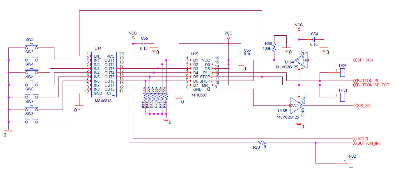
I'm just bringing up a new board with the attached circuit for pushbutton multiplexing. The microcontroller is a PIC18F4550. SPI_SCK and SPI_SDI refer to the PIC's hardware SPI peripheral. Basically the circuit uses the built in SPI capabilities of the PIC, with a dual tri-state buffer (U16), to read out the 7 pushbuttons through a parallel to serial shift register (U15). U14 is a switch debouncing chip that also provides an IRQ output (CH_) that goes low on any button state change. The BUTTON_SELECT_ line serves a few purposes to save GPIO pins on the PIC: it enables SPI communication to the shift register by enabling the U16 outputs, and it also triggers a load of the button states from the storage register inputs to the shift register on U15 via the STCP pin. Finally, it controls the output latches of the MAX6818, as taking the EN_ pin low drives the outputs. Taking EN_ low also resets the CH_ flag, which goes low on any button state change and then is reset to high on the falling edge of EN_. Because the MAX6818 tri-states it's outputs when EN_ is high, resistors R67-R72 are included to prevent floating inputs on U15. Also R66 is included so that the clock input SHCP is not floating when BUTTON_SELECT_ is high. The PIC SPI_SDI line also has a pulldown (not shown in the image).
The circuit works fine in regular operation, as I'm able to see the BUTTON_INT signal from U14 and then read out the pushbutton state by taking BUTTON_SELECT_ low and then high (to latch switch inputs into shift register U15), then low again and clocking out the data with SPI_SCK on the SPI_SDI line.
However, I'm seeing some very weird behavior from the circuit and I have no idea what is going on. Basically what is happening is that if the chip select line (BUTTON_SELECT_) remains high (i.e. U16 chip select deactivated) for more than a few seconds, then the whole system latches up somehow. The PIC microcontroller freezes (even pressing the master clear button MCLR_, which triggers a hardware reset, does nothing). The system current remains stable for a second or two after the PIC freezes, and then starts to ramp up by about 15 mA over the next few seconds, then drops rapidly back down to the quiescent level, after which the PIC resets. A few seconds after reset, the cycle begins again. All I need to do to prevent this behavior is to pulse the BUTTON_SELECT_ line low before the latchup occurs, which is certainly a workable solution, but at the same time I really need to understand the problem to make sure there are not other facets of the issue that I need to be concerned about. My first thought was some type of floating input issue, but I believe I've got everything tied down that could float, unless I'm missing something. Otherwise I'm fairly lost at this point and would appreciate any thoughts. Thanks in advance.
datasheets:
MAX6818 datasheet
**broken link removed**
**broken link removed**