win_win
Newbie level 4
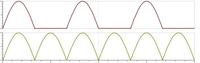
I have 2 questions below related to the full rectified waveform:
1. How to eliminate the negative cycle of the full rectified waveform?
2. We all know we can use a full bridge rectifier to get the full rectified waveform.
I am curious to know how to do it reversely, i.e., from a full rectified waveform to a sinusoidal one.
Could anyone help to contribute your idea to those questions?
Thanks a lot")
WinWin
1. How to eliminate the negative cycle of the full rectified waveform?
2. We all know we can use a full bridge rectifier to get the full rectified waveform.
I am curious to know how to do it reversely, i.e., from a full rectified waveform to a sinusoidal one.
Could anyone help to contribute your idea to those questions?
Thanks a lot
WinWin
Last edited: