Continue to Site

Welcome to EDAboard.com

Welcome to our site! EDAboard.com is an international Electronics Discussion Forum focused on EDA software, circuits, schematics, books, theory, papers, asic, pld, 8051, DSP, Network, RF, Analog Design, PCB, Service Manuals... and a whole lot more! To participate you need to register. Registration is free. Click here to register now.

27 MHz Amplification Query

Status
Not open for further replies.

RMMK

Full Member level 3
Joined
Jun 12, 2013
Messages
163
Helped
1
Reputation
2
Reaction score
1
Trophy points
18
Location
Karachi
Activity points
1,461
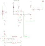
I followed a guide to built a small receiver and transmitter circuit working on 27 Mhz but its range is very small....... I tried to make a half-wave dipole antenna without much success...... I came across a circuit on the internet which seemed quite easy to built and is supposed to amplify my signal....... my question is will it work?? Will it increase the range and is it even a correct circuit diagram?? Image (3).jpg
 

Ah, No.

2n2222 with a 100V rail and 1 AMP Ic, SMOKING, literally.

You may wish to investigate the RD15HVF1 or RD16HHF1 and the circuits folks have designed to use them.
Grab a copy of experimental methods in RF design, ARRL Handbook, Radcom Handbook, Dye & Granburg, even a later edition Terman to see what you need to do.

Also what frequency and what mode, SSB has very different needs to FM for example.

For 10M band a local ham club should have someone willing to help, for 11M you have a type approval headache easier (And actually legal) just to buy a CB.

Regards, Dan.
 

Agreed, a 2N2222 is only rated at 75V so it would go pop even with no signal fed to it. Even if the transistors were sufficiently voltage rated, they would dissipate around 25 Watts each!

I'm interested in your half wave dipole, did you really make one 5.5 metres (about 18 feet) in length?

Brian.
 

Agreed, a 2N2222 is only rated at 75V so it would go pop even with no signal fed to it. Even if the transistors were sufficiently voltage rated, they would dissipate around 25 Watts each!

I'm interested in your half wave dipole, did you really make one 5.5 metres (about 18 feet) in length?

Brian.

Yup! I made one but i used a very soft wire therefore it sagged quite a lot!
Also here in my country there is no clubs like these! :-(

- - - Updated - - -

I felt that the circuit looked more like an audio amplifier than an RF power amplifier..... isnt an RF amplifier one on which inductors are used? Havnt studied RF amplifiers before!

- - - Updated - - -

Also in my application; where i can going to use these modules to carry control signal for movement of object (its a mini-semester project for Electronics course; even though i am a mechanical student and i take quite a lot interest in basic electronics courses) a long antenna is not an option. And i am thirsty for range!
 

Can we have the circuit of you existing TX? . Also the range of all transmitters are infinite, its just that the receivers can't pick up the miniscule signal. We do not know what power you have available or require. Also at this frequency layout and screening is importent or the amplifier will end up as being a high power oscillator.
So get hold of your favourite medium power RF transistor, like a 2n697 (bit poor) or a 2n3866 (brilliant). Connect the collector to +12 V via a 1K, connect the emitter to earth, connect the base to earth via a 1K and select resistors to go between the base and +12V just to cause the Vc to fall a bit, say to 11V. Now is the time to exercise your coil winding abilities! Wind a coil of about 20 turns around a 6mm former, spread the turns over 25mm. solder a tap on the windings at 5turns and ten turns. Connect the 5T tap to you existing RF source (and a earth to its case). Connect the 10T tap to the base of the transistor via a capacitor - any thing 100 PF-> 10 NF. Now you have to tune the coil to 27 MHZ, monitor the DC voltage drop across the 1K collector resistor, as the coil is brought to resonance, the volt drop will increase. So turn on and off you transmitter , see if you have a change in volt drop, if not put a small capacitor across the outside connections of the coil (20 PF), keep on incrementing the capacitor until there is a volt drop, then compress or stretch the coil to get a peak. Once the capacity is over 500 PF, then its obvious the coil is too small, try again with a 30 turn version. Once you have found the maximum. Switch off, copy the coil/capacitor and wire into the collector circuit replacing the 1K, 5T tap via a 1NF capacitor to the aerial, 10T tap to collector, 5T end to +12V, leaving the other end just connected to the tuning capacitor.
Now you need a diode probe to tune the coil, connect a small capacitor to the aerial connection as well as your aerial. connect the other end to a signal diode cathode, its anode going to earth. At this junction connect a 47K resistor. With you DVM measure the voltage between the 47K and earth and tune the collector coil for maximum output, as before.
Frank
 
Last edited:

Can we have the circuit of you existing TX? . Also the range of all transmitters are infinite, its just that the receivers can't pick up the miniscule signal. We do not know what power you have available or require. Also at this frequency layout and screening is importent or the amplifier will end up as being a high power oscillator.
So get hold of your favourite medium power RF transistor, like a 2n697 (bit poor) or a 2n3866 (brilliant). Connect the collector to +12 V via a 1K, connect the emitter to earth, connect the base to earth via a 1K and select resistors to go between the base and +12V just to cause the Vc to fall a bit, say to 11V. Now is the time to exercise your coil winding abilities! Wind a coil of about 20 turns around a 6mm former, spread the turns over 25mm. solder a tap on the windings at 5turns and ten turns. Connect the 5T tap to you existing RF source (and a earth to its case). Connect the 10T tap to the base of the transistor via a capacitor - any thing 100 PF-> 10 NF. Now you have to tune the coil to 27 MHZ, monitor the DC voltage drop across the 1K collector resistor, as the coil is brought to resonance, the volt drop will increase. So turn on and off you transmitter , see if you have a change in volt drop, if not put a small capacitor across the outside connections of the coil (20 PF), keep on incrementing the capacitor until there is a volt drop, then compress or stretch the coil to get a peak. Once the capacity is over 500 PF, then its obvious the coil is too small, try again with a 30 turn version. Once you have found the maximum. Switch off, copy the coil/capacitor and wire into the collector circuit replacing the 1K, 5T tap via a 1NF capacitor to the aerial, 10T tap to collector, 5T end to +12V, leaving the other end just connected to the tuning capacitor.
Now you need a diode probe to tune the coil, connect a small capacitor to the aerial connection as well as your aerial. connect the other end to a signal diode cathode, its anode going to earth. At this junction connect a 47K resistor. With you DVM measure the voltage between the 47K and earth and tune the collector coil for maximum output, as before.
Frank

here is the schematic of the transmitter:-
schematic-transmitter (1).png
 

The schematic is crude but it should work. Make sure you mount R7 as close as possible to the base of T2, the wiring length on it's IC1 side isn't so important.

L3 is used here to load the antenna, making the circuit think it is longer than it really is. That situation isn't as good as a full length antenna but it's better than nothing at all. If you can monitor the signal strength at the receiver and adjust L3 you should find it has a value that gives maximum transmitter power.

Brian.
 

With a long aerial, L3 actually reduces the output, You could try putting a small variable capacitor across it. Monitor the current taken by the circuit, best if its just the PA transistor. As L3 is tuned and more power goes up the aerial, the current should rise, tune for a peak.
Frank
 

how can i make an even powerful RF power amplifier the supplement it for increasing range? I will try tinkering with the L3 after i receive a variable inductor from the online supplier! As for the taping inductor solution; i am not very good in building inductors because last time i build one tuning the LC tank and it didnt help so i went for the variable capacitor and inductors option that time! :wink:

- - - Updated - - -

Also i have observed that the switching signal i transmitted from the transmitter using 555IC (in this case 350Hz) had on the receiver end after the comparator stage went 100 Hz in addition! last time I checked it using oscilloscope it was around 450Hz (I cant check it now because my university is off and i am in vacations). I was looking to use it for wirelessly controlling my servos by transmitting control signal of specific pulses from 555 but it seems like it wont do the job as it is and i might have to use some other way with this circuit...... but for now i desperately want to increase range! Is there any option of cascaded amplifier stages?
 

Why are you using such a low frequency if small aerials are important to you?
433MHz kit is off the shelf and needs a much smaller aerial system and 2.4 or 5Ghz stuff can be had.

Power amplifieres are of course possible, and there are plenty of designs out there for broadband solid state PA strips up to many hundreds of watts, but going there is the wrong answer to your problem.

73 Dan.

maybe because i want to learn new things especially RF Power Amplifier design..... I just dont want to copy a design i also want to learn how to design them...... I would highly appreciate if i get to know an easy approach to design them!
Thanks
 

You need to analyze the problem before looking for solutions. More power will not necessarily improve your signal. The clue is in the other frequencies you could see at the receiver. As an experiment, try turning the transmitter off altogether and see what comes out of the receiver, I think you will find you still have a signal!

The transmitter is 'OOK' (On Off Keying), in other words it transmits a carrier when the modulation signal voltage is high and turns the carrier off when it is low. It does this by using the modulation to provide the bias to the output transistor, no bias means no output, except for a tiny amount of leakage through stray capacitance.

Consider what comes out of your receiver when the transmitter is turned off, you will see exactly the same 'interference' when the modulation voltage is zero. So although you transmit 350Hz, what you receive is carrier when the 555 outputs a high and interference when it outputs a low. Adding a power amplifer will still give no output when the carrier is off.

There are several solutions to the problem but before looking at them, tell us how the signal is supposed to operate the servo systems, for example are they proportional controlled (PWM) or frequency controlled and how many servos are there?

Brian.

Yup... I am trying the PWM option! and possibly i would be using 4 servos but i thought i would try to control each servo using RC at different frequencies!

- - - Updated - - -

schematic-receiver (2).png
Here is the actual receiver schematic...... i figured it would tinkering to control servo!
 

That's a superegenerative receiver so it will produce random output in the absence of a strong carrier. They are notoriously noisy by the nature of the way they work but they also very sensitive. You may note similarities with the transmitter circuit, in fact the receiver will produce significant interference to other nearby receivers so if you go for the different RC frequencies aproach you will have to keep them well apart from each other.

I'm not sure the 555 at the output section will work in a PWM application, I think it's working as a flip-flop so the output will be a square wave regardless of the mark/space ratio of the transmitted signal. Try it and see.

You can make some improvement by partially biasing the second transistor through a resistor from the supply rail so instead of the carrier going completely off, it drops to a lower level. This makes it an AM transmitter which has the advantage in your application of always giving the receiver something to hear so it quietens it. You should still be able to recover the changes in signal level even though they are somewhat reduced. A better option is to use FM although the transmitter and receiver will be a little more complicated. FM lets you use the full power capability of the transmitter and has far better immunity to interference from other sources.

For multiple RC servos, consider a different method altogether: instead of transmitting the PWM itself, send commands to the receiver and tell it to generate the PWM locally. This allows you to add addressing over a single frequency, for example sending "S4=123,S1=45" to make servo 4 move to position 123 and servo 1 go to position 45 although the actual 'wording' of the command is up to you of course. It forces you to use a microcontroller but the workings of the program are fairly simple.

Brian.
 
  • Like
Reactions: RMMK

    RMMK

    Points: 2
    Helpful Answer Positive Rating
thanks for this solution...... i was also thinking of doing the same i.e., generating PWM locally rather than transmitting it!

- - - Updated - - -

but one thing keeps bugging me is that isnt it okay even if the receiving signal is full of noise because I think what if i send these switching signal and operate a relay driven circuit on the receiver end it wouldnt mess up right?? but on the microcontroller solution i think noise will be wreck it......... But first i want to increase the range!

- - - Updated - - -

for FM..... all i found on the internet were some audio voice transmission circuits over 5 kms of range
 

The advantage of FM is the carrier is always present. You may have noticed the output of your present receiver is random until it hears a carrier then it quietens down. In FM the carrier is always present so the noise is less. However, it introduces problems of it's own but these can be overcome by using error protection tricks.

I use 5mW FM transmitters in tiny plastic boxes, powered by a small PV cell glued to the lid and get perfect data transfers over >100m distances with an antenna only about 3cm long at the transmitter and about 10cm long at the receiver. I use 433.92MHZ so the antennas are shorter than yours at 27MHz but it shows what can be achieved.

You originally mentioned this was for RC but in your last post you mention operating a relay. RC normally uses proportional control but you don't need that if you only want to control relays. Be careful what you are aksing for, do you really want more power or more reliabilty? They are not the same thing!

Brian.
 

Its not like i need more power if i get the range and also of-course reliability is desirable..... I mentioned relays because i was thinking of another possibly more simpler solution without using uController that is using 555 timer IC's to control servo's deflections. The relay would come in handy to trigger the required pulses for that scheme! By the way can u show me ur schematic of FM transmitter and receiver you use??
Thanks
 

The units I use are here:
https://www.rfsolutions.co.uk/acatalog/FM_Hybrid_Transmitter___Receiver_Modules.html

I use the FM-RTFQ1-433P and FM-RRFQ1-433P, they are cheaper to buy than make.
My application monitors water tempeature using a submerged DS18B20 sensor and uses a PIC12F1822 to manchester encode the data for transmission. The receiver output goes to another PIC12F1822 which decodes back to the original data and interfaces it to a control bus. There are 8 temperature sensors, one battery voltage monitor, an RFID door entry system, and several pump control circuits on the same system.

Brian.
 

This module is not available in my country and the delivery costs for the same is quite high.... but i have this cheap one with me!
https://www.electrodragon.com/product/433m-rf-wireless-module-a-pair-of-receiver-and-transmitter/

But sir i really want to work around and learn with this 27MHz setup......

- - - Updated - - -

I was thinking if i place another 2N2222 transistor in a configuration as is T2 (in the transmitter circuit diagram) with the same set of inductors and capacitors in a cascaded fashion in front of T2 will it amplify my signal without much of distortion? Will the signal strength will increase? And how was this designed in the first place? I am familiar with Class A & B audio amplifiers but dont know the theory behind these RF ones......

- - - Updated - - -

By the way I have biased the transistor T2 with a resistor as u said and it seems the output at the receiver side has stabilized a bit!

- - - Updated - - -

By the way sir ur application is great! I am working on my Gas Turbine engine to be developed for my FYP! And for controlling various systems on it I needed to remotely control them using servos! The Gas Turbine is complete and we are working now on to install it on a Remote Controlled Car. The Gas Turbine will be the prime mover for it! Since no one wants to sit on an experimental project I figured it needs to be remote controlled! For this reason i am asking for ur help to achieve long range so that we may move it far from any hazardous place and our vicinity! but for now this RC is a mini-semester project for me as well!
 

.....the range of all transmitters are infinite, its just that the receivers can't pick up the miniscule signal......

chuckey frankie chuckey chuckey... LoL !!
Once the (weak) signal fades below the noise floor level.... then what ?
 

Status
Not open for further replies.

Part and Inventory Search

Welcome to EDABoard.com

Sponsor

Back
Top