Continue to Site

Welcome to EDAboard.com

Welcome to our site! EDAboard.com is an international Electronics Discussion Forum focused on EDA software, circuits, schematics, books, theory, papers, asic, pld, 8051, DSP, Network, RF, Analog Design, PCB, Service Manuals... and a whole lot more! To participate you need to register. Registration is free. Click here to register now.

[Moved] simple HF 30MHZ wave

Status
Not open for further replies.

newbee2014

Newbie level 2
Joined
Jul 9, 2014
Messages
2
Helped
0
Reputation
0
Reaction score
0
Trophy points
1
Activity points
14
Hello all.
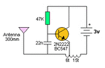
I'm learning how HF waves work.
I just want an emitter who sends a wave (30mhz)to a receiver.
So I wanted to know if my schema is right.
And how to make the receiver part please?.
Thank you all. diagram1.jpg
 

If the resonator is a standard 3 pin type it will not work. A resonator is a component that exhibits a change in the way is passes a signal from it's input pin to output pin at a specific frequency but it doesn't generate the signal itself. Think of it as a gateway that opens to signals at the resonant frequency but closes to others. To make it produce a transmittable signal you have to include it in the feedback path of an oscillator then couple the oscillators output to the antenna.

Brian.
 

Dear Brian.
Thank you for your answer.
Can you help me with a schema please.
Btw,I found out this(without resonator),maybe I can build it but I can't
(90mhz emitter).

find the receiver.
Sincerely newbee2014
 

Attachments

  • simple.gif
    simple.gif
    2.7 KB · Views: 59

Dear Brian.
Thank you for your answer.
Can you help me with a schema please.
Btw,I found out this(without resonator),maybe I can build it but I can't
(90mhz emitter).

find the receiver.
Sincerely newbee2014

I answered you receiver query in the other forum

----- a standard $5 AM/FM band radio receiver -----

cheers
Dave
 

Follow Dave's advice with the receiver, when they are so cheap there isn't much point in building your own.

Your original circuit used 30MHz although I'm not sure why you chose that frequency. It lies on the border of short waves and VHF so a suitable receiver would be difficult to find. If you change to 90MHZ it falls in the domestic VHF broadcast band so receivers are plentiful.

The schematic you show in post #3 might work but it is likely to be unpredictable in operation. There are several reasons but the main one is the frequency is decided only by the tuning coil. The coil isn't just the curly 'turns', it includes the wires at each end of it and one end is the battery wire. It follows that the length of battery wire changes the frequency - not a clever idea!

There are ways to fix the problems but all will make it considerably more complicated. You also have to be very careful with the component layout and wiring lengths as you work at higher frequencies so your construction techniques become very important. I suggest you stay with the 90MHz idea but look for a design (plenty on the internet) that includes a component layout and in particular look for one that does not connect the antenna directly to the tuning circuit. There should be at least one transistor amplifier stage between the source of the 90MHz (the oscillator stage) and the place the antenna connects to, otherwise you will find the antenna length and things moving nearby to it will make the frequency drift.

Brian.
 

Status
Not open for further replies.

Part and Inventory Search

Welcome to EDABoard.com

Sponsor

Back
Top