Continue to Site

Welcome to EDAboard.com

Welcome to our site! EDAboard.com is an international Electronics Discussion Forum focused on EDA software, circuits, schematics, books, theory, papers, asic, pld, 8051, DSP, Network, RF, Analog Design, PCB, Service Manuals... and a whole lot more! To participate you need to register. Registration is free. Click here to register now.

Water conductivity measurement

Status
Not open for further replies.

north2012

Member level 3
Joined
Apr 1, 2013
Messages
63
Helped
1
Reputation
2
Reaction score
1
Trophy points
1,288
Activity points
1,813
Hello,

I would like to determine conductivity of water with complex impedance measurement based on AD5933. I do not have very good electro-chemical background so I am not sure how to connect impedance (magnitude, phase angle) with conductivity.

Any tutorials or practical experiences?

Thanks.
 

Interesting topic, one question, why you want to measure the complex impedance of water instead of just the dc-resistance?
 

Thank you for your reply.

I am using AC because DC current will produce polarization of liquid.
 

Agree, ok, so you're interested in the resistance of water or really in the complex impedance?
 

Sorry, but I am not sure that I understood you well... If I have calculated complex impedance, is there any correlation with conductivity?
 

The dissipation factor or Loss Tangent or complex impedance of water can be done with high voltage if in the GΩ range, but constant current is best method then use PLL quadrature detector to measure VI directly or use phase angle vectorfrom a phase detector and measure amplitude of voltage from CC source.

. Omega Meters tend to use high voltage for board range of leakage resistance which is important due to ionic and particulate matter contamination such as sodium and metallic particles. The dielectric constant is fairly constant but varies with frequency. Instruments have been designed to measure complex impedance from 0.01 Hz to 1MHz to measure the water content in mineral oil used in HV transformers, but 10 Hz gives useful results or far away from AC stray noise. (AC Notch filter or tuneable BPF and very high CMMR may be required. The conductance per unit volume is the std method I believe.
 
Last edited:

Maybe you tell us a little bit more about your application, you want to measure the cond. of water in a can or of the ocean :)? Should it be a continous measurement or just at specific time periods (e.g. one time per day). Do you need a very precise measurement?
 

If a DC voltage is applied, ions would build up an "ion cloud" near the surface of the electrode. This would prevent other ions in solution from being attracted to the electrode.

This is referred to as the "polarization effect". Therefore, AC potentials are utilized to prevent localized build up of ions. The AC driven signal can be operated between 2-10 volts at 60 Hz-3,000 Hz, with lower frequencies being used for lower concentrations like 10Hz.
 

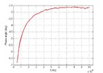
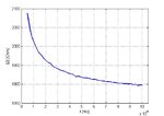
I have attached my results which I obtained today.
I used simple structure of two copper lines separated on FR-4 substrate to have constant distance between electrodes. Using my complex impedance system I varied frequency in range from 5 to 100 kHz (constant temperature).
This is magnitude change
z.jpg

and phase angle change
phase angle.jpg

How I can measure conductivity based on this results? For example, I will use distilled water or other liquid with known characteristics for calibration but how later to determine on unknown liquid?
 

Because of high conductivity and low phase angle, you might try a sweep from 1 to 100Hz.

What is the plot with just air? capacitance of the track pair is ? vs capacitance of water?

Do you care about dielectric constant polarization effects or just resistivity?

If just resistivity, then the polarization current must be much smaller than the ohmic current ,which implies very low frequency.

Did you use constant current AC signal in your measurement?

Show your measurement details please.
 
Last edited:

Hello SunnySkyguy,

Thank you very much for your replies.

I am not able to perform sweep beyond 1 kHz because I am using self-designed impedance analyzer based on AD5933. Plot when capacitor is in air is very huge resistance, in range of MOhms and GOhms... I am not sure if I can calculate capacitance of structure with simple equation like I presented in post

https://www.edaboard.com/threads/315684/

OK, topics are connected but have different sense.
I would like to measure conductivity or complex permittivity.
 

Hello SunnySkyguy,

Yes, I will make temperature compensation of obtained results. But I still do not have idea how to connect complex impedance with permittivity/conductivity?
 

Did you check correct operation of your impedance measurement by connecting a fixed resistor or RC parallel circuit?

Presuming the results are correct, it's obvious that they can't be converted to frequency independent complex impedance or permittivity. You can of course calculate the elements of an equivalent RC circuit for a given frequency. The phase deviation is however small enough to take the impedance magnitude numbers as resistance and convert it into conductivity, preferably for a frequency in the standard low kHz range.

I don't know the geometry factor of your conductivity cell and what the 2 kOhm numbers mean in µS/cm terms.
 

Yes, I checked operation of complex impedance measurement system with a lot of different RLC combinations. Magnitude error is less 1 % while phase angle error is about 1.5%.

I would like to convert it to frequency and temperature dependent complex permittivity.
 

So you are just asking about the arithmetic? It should be obvious from definition of complex permittivity, except for the cell geometry that must be empirically determined.

I presume you have no problems to convert the impedance measurement from polar (magnitude, angle) to cartesian coordinates (Z = R + jX) or admittance (Y = 1/Z = G + jB).
 

The cell geometry I will determined with distilled water, for example.

But how to move on? It is not a problem to move in Y = 1/Z = G + jB from Z and Theta, but still I can not reach how to connect conductance and susceptance [Siemens] with complex permittivity?

Thanks.
 

Hello FvM,

Thank you very much for your replies.

This will helps a lot but I still can catch how to estimate A, even if I am using a liquid with known dielectric permittivity and know dimensions of capacitor.
I will calculate G and B (based on R and X) and then I have

σ=A/G (A is still unknown)

ε'=-B/(Aω)

I can not estimate A from the first equation because I do not know σ...
 

You claimed to calibrate the cell with distilled water...

In any case you either need to know the geometry factor (e.g. from a numerical field calculation) or calibrate with a conductivity standard. KCl solutions with e.g. 100 µS/cm or 1000 µS/cm are commonly used. Distilled water would be too inaccurate I presume.
 

Status
Not open for further replies.

Similar threads

Part and Inventory Search

Welcome to EDABoard.com

Sponsor

Back
Top