tictac
Full Member level 5
hi
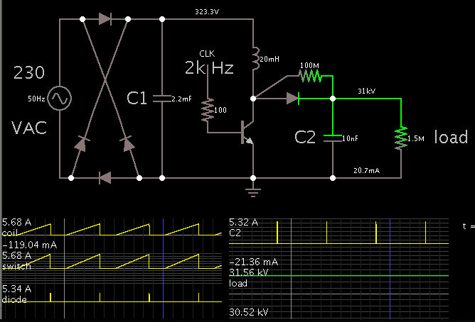
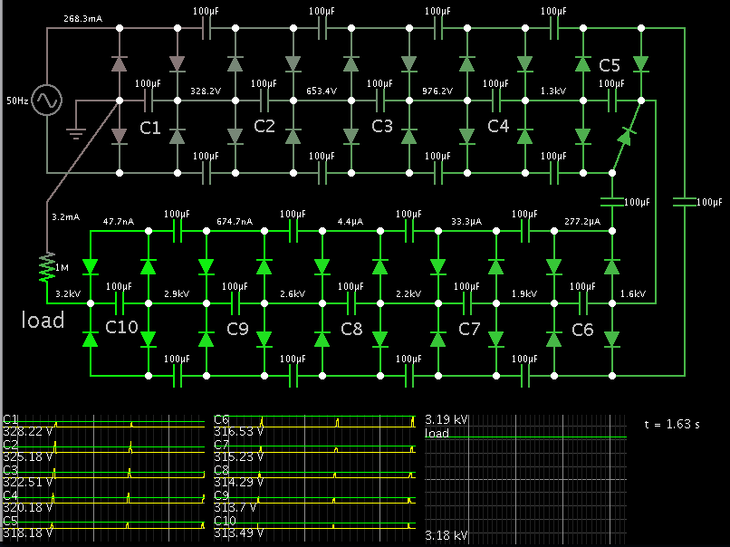
I want to design the smps with below specifications:
Vin=220 Vac
Vout=1KV to 30KV , Iout-max= 20mA
I want to use LLC for it. Is it possible to use LLC for this converter? I want to calculate resonance elements and transformer turn ratio and primary and secondary turns and inductances. The maximum voltage and current that drop on resonance elements at the primary side. Is there anybody to help me for calculating its parameters?
Regards.