Continue to Site

Welcome to EDAboard.com

Welcome to our site! EDAboard.com is an international Electronics Discussion Forum focused on EDA software, circuits, schematics, books, theory, papers, asic, pld, 8051, DSP, Network, RF, Analog Design, PCB, Service Manuals... and a whole lot more! To participate you need to register. Registration is free. Click here to register now.

NiMH solar battery charger- need help

Status
Not open for further replies.

dany.1986

Junior Member level 1
Joined
Feb 26, 2010
Messages
19
Helped
0
Reputation
0
Reaction score
0
Trophy points
1,281
Activity points
1,427
Hello everyone, I am currently working on a solar charger project (to charge a NiMH battery which has a nominal voltage of 1.2 V and 1300 mA capacity) and I have come across some problems that I don't fully understand. My solar panel provides 2.14 V and 1.4 A. However, when I insert the battery, the solar panel voltage drops to 1.5 V (it is actually better for the battery under charge as the maximum charge voltage is 1.5 V as stated in the datasheet). Can someone explain me why the voltage drop happens? Do I also need a diode to protect the solar panel against reverse current from the battery or the MOSFET transistors give this protection? Below is the circuit. Thanks.
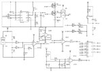
Solar Battery Charger.jpg
 

Thank you. In this case how can I determine the solar panel voltage operating under the load? In my design I have six solar cells each providing 1.1 V (open circuit) and 440 mA (short circuit). I divided the cells into two sets, each having three cells connected in parallel. Then I connected these two sets in series. This configuration gives me the panel output of 2.14 V and 1.32 A. For load I am using 1.3 A rechargable battery with 1.2 V nominal voltage. I don't think that my control circuitry can be considered as a load too? Am I right?
 

You must string together enough PV panels in series, to overcome battery voltage.

I have a PV panel designed to charge a 12V battery, and it puts out 22V open circuit. (However when I hook it up to a battery, the voltage automatically drops to the battery voltage.)

Furthermore you should not expect 440 mA charge rate (which is what you measured short circuit). Because then the voltage is near zero, and no power is transferred.

You will need to experiment, to find out how many solar cells in series, will give you a suitable charge rate into your batteries.
 
Can you tell me why the voltage drops to the battery voltage? Is it always going to be the case when solar panels are used for batteries charging?
 

Batteries have a very low effective series resistance (ESR) which rises with low charge levels and end of life sharply.

PV panels have high impedance like current sources but not constant. Often maximum power transfer is around %75 of Vmax.

The voltage will be controlled by the part with the lowest impedance, but OHm`s Law can be applied using ESR of each part for a linear approximation, using RdsON , Rbat, etc. When rapid PWM switching, inductive impedance of wires and ESR Cap get involved.
 
Thank you. Could you tell me how to actually calculate what the voltage drop would be when the battery is inserted? The output from my solar module is 2.14 V and after the battery is inserted it drops to 1.5 V and current of 1.3 A flows through the circuit and charges the battery. The battery that I am using is 1.2 V 1300 mAh. Its internal resistance is in range 17-38 mΩ.
 

The ESR drops with rising State of Charge and rises also with aging.

A NiCd AA might have an ESR in the ~ 30 mΩ range @ 100% SOC or fully charged, but 10x higher at 0% SOC
A NiMH AA might have an ESR in the ~ 300 mΩ range @ 100% SOC

So ESR is an indicator of SOC, thus if you can measure ESR, or if you know SOC then you can predict voltage drop. in the range 10~90%

There are some non-linearities when over-charging or over-loaded and undercharged where ESR rises sharply.

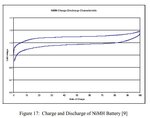
Hysteresis loop below depends on Capacity and shown for 1.2C (120%) below for rapid charge discharge cycle.

nicd.jpg

ref https://kb.osu.edu/dspace/bitstream...d=0BDECA5E39475FF5E9E78DA782513BCF?sequence=1
 

I appreciate your help, however, how can I calculate the voltage when the load is inserted? Do I calculate it using the Ohm's Law? If yes, then assuming battery resistance at 0% SOC= 1.2 Ω, the current at the maximum power point= 1.3 A therefore V=IR, V= 1.56 V (voltage at the solar panel). Am I right?
 

The PV panel has an internal impedance. This is the reason the voltage drops when you attach a load (a resistive load).

Attaching a battery creates a few differences compared to attaching a resistive load. The battery voltage appears across the battery. In effect, the battery voltage dominates.
 

I appreciate your help, however, how can I calculate the voltage when the load is inserted? Do I calculate it using the Ohm's Law? If yes, then assuming battery resistance at 0% SOC= 1.2 Ω, the current at the maximum power point= 1.3 A therefore V=IR, V= 1.56 V (voltage at the solar panel). Am I right?
Not quite

If it were linear with an initial voltage, Vi then Vbat=Vi + I*ESR and solar panel would drop to whatever the battery voltage yields dfor the available current since the PV is a higher impedance current source. But note from my curves it is only linear over a small range. So you need to get sophisticated to curve fit and compute this value of SOC or use a look up table
 

I suspect you do not have the chart SunnySkyguy mentioned, so you can do as BradTheRed suggested and experiment.

As a starting point, you could find a similar chart as I posted, and extrapolate.
 

Status
Not open for further replies.

Part and Inventory Search

Welcome to EDABoard.com

Sponsor

Back
Top