SKEB
Newbie level 3
Hi all,
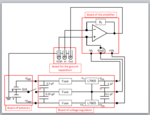
In order to measure the low noise of a device at a negative voltage between -5V and -1V, I developed the following circuit:
- Transimpedance amplifier using OPA656U from Texas instruments that functions at Vs=-/+5V.
- A circuit with two voltage regulators (negative and positive) that regulate from -/+12V to -/+5V.
- Batteries
- Board for the ground separation
The purpose is to shift the ground of the power supply to the voltage of the Keithley230’s (K230’s) and let –Vs and +Vs follow that shift by adding their voltage values to -/+5V.
In order to do this, we separated all the grounds of the board with the amplifier from the ground of the power supply that will be on another potential (the potential of K230). Moreover, we disconnected the ground of the batteries from the regulators and connected it to the ground of the K230.
Thus, the results obtained for a voltage of -3V for example on the K230 must be on the power supply as follows :
-Vs = -5-3 = -8V
Gnd = -3V
+Vs = +5-3 = +2V
However, the results obtained are :
-Vs = -5V
Gnd = -3V
+Vs = +5V
The circuit looks correct on paper but when developing it, it is not working.
Any idea about the strange values obtained ?
Kind regards,
SKEB