Ogu Reginald
Full Member level 6
I found some issues with your design.
1) You did not drop voltage on SG3524 to 12V. 7812 voltage regulator can not work beyond 36V. A series transistor regulator ahead of 7812 will drop voltage to 24V for input of 7812 regulator . For example a setup like this will also provide supply for 12V relays (which are more common and cheap) and any other circuit such as status display.
http://obrazki.elektroda.pl/838586830
You know 48V is four batteries in series. After the first two batteries (counting from ground), I tapped a 24V and it is this 24V that I used to power my electronic circuit (I regulated the 24V to 12V).
Corncerning the MOSFET, I have used 80N30W and the problem still continued.
[COLOR="silver"][SIZE=1]- - - Updated - - -[/SIZE][/COLOR]
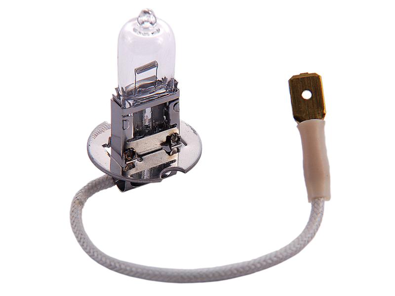
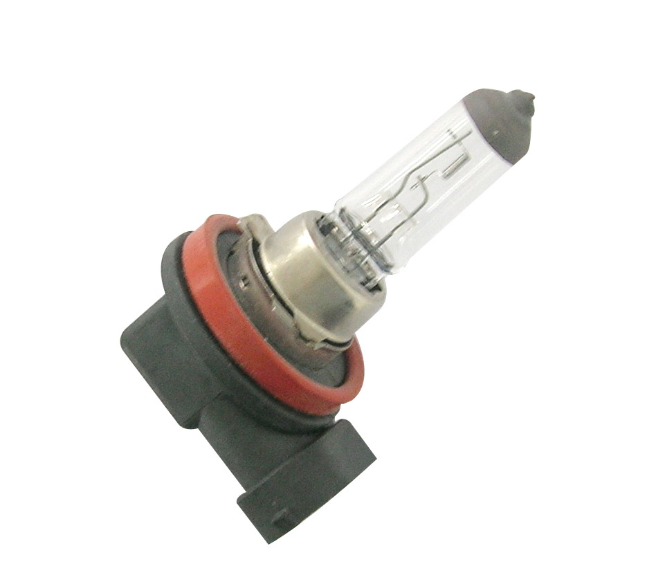
[QUOTE="pradeep.g.belchada, post: 1284096, member: 86265"]in series with the battery 48v (+ve wire of inverter to battery) conect 50watt 12v motorbike bulb. and give full 48v to the inverter. at this time dont conect the load . see if their is a 230v o/p. this method will safeguard the mosfet[/QUOTE]
I didn't see a 50watt bike lamp but instead I saw a 21watt. Can i use the one I saw?