Continue to Site

Welcome to EDAboard.com

Welcome to our site! EDAboard.com is an international Electronics Discussion Forum focused on EDA software, circuits, schematics, books, theory, papers, asic, pld, 8051, DSP, Network, RF, Analog Design, PCB, Service Manuals... and a whole lot more! To participate you need to register. Registration is free. Click here to register now.

Help/Circuit needed to disconnect power line and injecting AC test voltage to heater

Status
Not open for further replies.

El_Paco

Member level 1
Joined
Mar 7, 2002
Messages
38
Helped
1
Reputation
2
Reaction score
1
Trophy points
1,288
Activity points
363
Hello,
some advice is needed


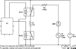
Old system (see picture):
1. a heater is connected to power (24 V) by 2 relays as shown in the circuit.

2. later the heater is disconnected for short times from power

3. ac voltage of 5 V is applied

4. the current of the voltage is measured for detection

5. heater is again connected to power


new system should be realised with semiconductors because of the space limitation.

possible solutions:I
1. usage of transistor as switching elements --> hint : power loss --> Uce = 0,7V / I = 24V/4R=6A --> P(transistor) = 4,2W

2. usage of Mosfet instead of relays --> hint : body diode between Drain - Source -> conduction in reverse polarity....


someone has some advise?

best regards,
Frank
 

Attachments

  • principle.png
    principle.png
    30.7 KB · Views: 54

1) As you note, you can't use a MOSFET for switching AC (without playing some games, which I don't think you want to do)
2) Maybe I don't understand your application, but why can't you measure current with the 24VDC connected?
3) Why do you need to measure current with AC?

But if you MUST do things this way, look at using solid-state relays, for example:http://www.clare.com/home/pdfs.nsf/0/E6D9BA0F358C71CD85256F3500603044/$file/CPC1909.pdf
 
Hello Barry
many thanks for your answer.

2.) i could not measure the current - because a +/- Ac signal in a range of +/- 5V is applied to one of the wire by high impedance- with 24 V connected ac test voltage the signal is destroyed

3.) sorry - confidential..... could not explain more

solid state relay is a good advice - at this point i come to

1.) playing some games - as i see a solid state relay for AC are 2 antiserial connected FETS (more or less)
It't possible to use two n'fets ?
have you some schematics for this - what are the hints?

@chuckey
sorry for the incorrect circuit..... in reality some parasitics elements are measured between GND and the isolated Heater.......
The second relay is for ground isolation......


best regards,
Frank
 

I have never tried to build this type of SSR out of discrete MOSFETs, but I suppose you could try. The main issue, as I see it, is that you have to drive the gate of the upper FET 5-10V higher than its source (the output voltage) in order to turn it on.
 

If you return the signal "earth" directly to the bottom end of the heater, It should all work without RLY2. If I understand your requirements correctly, I would put a PNP transistor in series with the +24V line (C-> load, E -> +24V). Now you can switch the load current off, by switching off the base current, which also puts a high impedance between the load and the +24V, so it should not cause your 1KHZ to go into the PSU. Connecting another transistor (NPN) between earth and the base with a current limiting resistor in series with its collector feed, will allow the controlling transistors base current to be controlled from the base of the second transistor from U1.
Frank
 

Status
Not open for further replies.

Similar threads

Part and Inventory Search

Welcome to EDABoard.com

Sponsor

Back
Top