Continue to Site

Welcome to EDAboard.com

Welcome to our site! EDAboard.com is an international Electronics Discussion Forum focused on EDA software, circuits, schematics, books, theory, papers, asic, pld, 8051, DSP, Network, RF, Analog Design, PCB, Service Manuals... and a whole lot more! To participate you need to register. Registration is free. Click here to register now.

Boost Converter analysis

Status
Not open for further replies.

Eshal

Advanced Member level 1
Joined
Aug 29, 2012
Messages
470
Helped
16
Reputation
32
Reaction score
15
Trophy points
1,298
Location
Nowhere :)
Activity points
5,149
Hello experts!

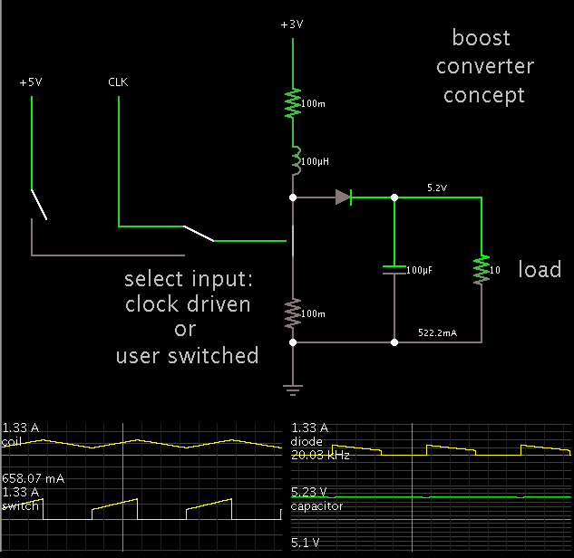
Here is my new thread about Boost converter.
Here is its schematic.
Boost Converter.PNG
Here is mode 1 (When S is On)
mode 1.png
Here is mode 2 (When S is Off)
mode 2.png

Given:
Vs = 3V
Vo = 5.2V

Find:
value of inductor (L) = ?
Value of capacitor (C) = ?
Value of Resistor (R) = ?
Which Diode (D) should be use = ?

Assumptions:
Ideal switch that's why MOSFET or BJT or IGBT is replaced with SPST switch.

Experts, I want to design it. If there is any lack of information about this circuit for designing then let me know. But I want help and please be specific with post and title. Ofcourse you are mostly professionals but I am a learner so sometimes you talk very high which I could not understand and they are passed over my head. So please try teach like you are teaching in the class room and exams are on the head and you need to cover the most important points.

Thank you very much.
 

Specify these values,what is your desired:

  • Diode Voltage Drop
  • Frequency
  • Output Current
  • Minimum Output Current
 
  • Like
Reactions: Eshal

    Eshal

    Points: 2
    Helpful Answer Positive Rating
Thank you sir,

Diode Voltage Drop:
It must be 0.7V for Silicon Diode. Isn't it?

Frequency:
You mean switching frequency?
I am not sure about this, how much it could be. So I want to ask you what do you think that which frequency is better to choose?

Output Current:
500mA

Minimum Output Current:
320mA, at least

Does this help you sir?

And let me know if you think I am wrong somewhere.

Thank you.
 

I took 5% voltage ripple & generally frequency around 500KHz is good. Diode drop = 0.7 V

Duty cycle = 5.2 - 3/5.2 = 42.3% L = 10.0578 uH,C =2.10 uF

You do know o/p voltage & required load current,you can find out value of R.

-----------------------------Diode Recommendation---------------------------------

  • By the way,why do you want to use a Si diode with a voltage drop of 0.7,why don't you try to use a Schottky diode with a low forward voltage drop & a forward current greater than the peak inductor current and one with reverse voltage rating greater than Vout.
  • Generally Schottky diodes are used in dc/dc converter designs.
 
Last edited:
  • Like
Reactions: Eshal

    Eshal

    Points: 2
    Helpful Answer Positive Rating
OMG... It is much simplified.
OK so your name is rahdirs. Hello rahdirs.
Thank you for this. But I can do all these calculations too myself. Actually, I want to know why it took 5% of voltage ripple? And what about current ripple by the way? You took voltage ripples into account but didn't discuss current ripples. Does this mean we can neglect current ripples. Huh?
And why 500KHz Switching frequency is good?

Are these formula you used for:
Duty Cycle (k) = (Vo - Vs)/Vo ?
L = (1 - k)R/2f ?
C = (1 - k)/16L(f^2) ?

The formulas I show above for L and C are the formulas for finding the critical values of L and C. Did you also use these? If not then my formulas are also applicable too, right?

Your recommendation about diode is just new to me. I didn't know this fact. Schottky diodes are used in DC to DC converter because the have forward current greater than the peak inductor current. Can you elaborate how this could be helpful in choosing Schottky rather than normal silicon diode. Huh?

Thank you for great post.

@BradtheRad
Thank you sir, I have read this article already. It helped me alot. But this is my first time designing of Boost converter so I decided to take help.
 

  • The switching frequency of approx. 500kHz is generally considered good.
  • In general, in both boost and buck switching regulators, a higher switching frequency allows the use of physically smaller inductors and capacitors.
  • However, a high switching frequency can also reduce the overall efficiency of the regulator,through switching losses both in the switch itself and in the gate-drive circuit.The diode also contributes something to switching losses.
Try reading this thread from Edaboard on kind of diode to choose based on your req. for a boost converter:https://www.edaboard.com/threads/217405/,

Yes,i used that formula for duty cycle.I took ripple current to be 40%.Sorry for forgetting to write about current ripples,we do not neglect them.Then calculated L from iL pk & iL min & Capacitor value from On time of switch,load current,discharge of 3%.
 
  • Like
Reactions: Eshal

    Eshal

    Points: 2
    Helpful Answer Positive Rating
Hello.
Nice thread you mentioned. It gives information for diode. I got what contributes to switching losses. But as you said, higher switching frequency reduces overall efficiency too. So is there any method to overcome it?
And you took ripple current 40% and ripples voltage 5%. Why is it so? Please explain to a dumb student :p
And I think you used waveforms in order to calculate L and C values.
I want you to explain this sentence, please
Then calculated L from iL pk & iL min & Capacitor value from On time of switch,load current,discharge of 3%.

Thank you.
Regards,
Princess.
 

I made an interactive animated simulation of a boost converter which takes 3V and steps it up to 5V at 500mA.


This link will load the above schematic onto your computer, and run it onscreen.

https://tinyurl.com/pxzfu6z

(The website falstad.com/circuit will open. It may ask you to permit the incoming connection.)

To activate the power cycle, click the switch at the extreme left, then let up.

Observe how the waveform through the coil rises when you press the switch, then falls when you let up.

Before long you will get an idea what tempo to maintain, in order to deliver your specified voltage and current at the load.

I used a 10 ohm load, to draw 500 mA at 5V.

I used a 100uH coil. It is compatible with a 20 kHz frequency which is often recommended because it is above the range of human hearing.

However you can alter this value, by right-clicking and selecting Edit.

By experimenting you will get a better idea what values go with what frequency and duty cycle, etc.
 
  • Like
Reactions: Eshal

    Eshal

    Points: 2
    Helpful Answer Positive Rating
-----------------------Choosing Switching frequency---------------------------------
  • For SMPS, there is a trade off between switch ripple and switch loss. If switch frequency increases, the smaller components can be chosen and faster response of the system can be achieved.However, it will increase the switch loss.
  • You can always use lower switch frequency but you will have low efficiency.Choice of switching frequency is a trade off between switching losses and fast transient response.
  • But you can some-what reduce switching losses by "Soft Switching", and/or "Low Losses/Non Dissipative Snubbers".
You can maybe use soft-switching to have lower losses & also low EMI.

------------------------------------Ripple Current---------------------------------------------
  • The ripple current that i've written is the optimal ripple current of the inductor. The inductor current ripple ΔIL is typically set to 20% to 40% of the maximum inductor current. Ripple current of inductor is the rms value of current flowing through an inductor.
  • In boost circuits there is always a ripple current through the output inductor as a result of the inductor charging and discharging as the series switch is periodically closed and open.
  • If the ripple is large enough the current may actually drop to zero when the switch is open indicating that the inductor has discharged completely. As you lower the switching frequency the inductor current has a bigger and bigger ripple,due to long periods of discharge.
------------------------------------------Ripple Voltage-----------------------------------------
  • The boost converter output capacitor has to keep the output voltage high when the inductor is being charged (and is hence disconnected from the output). Therefore there will be a component of the output ripple due to the discharge of the output capacitor.
  • In addition, when the inductor is discharging, the output capacitor will experience an inrush of current and any ESR (effective series resistance) in the capacitor will also result in ripple.
We would like to keep output ripple low say,5%(ppl even take 1%).

-----------------------------------------Calculations---------------------------------------------

Then I've used basic formula , V = L*di/dt & I = C*dv/dt.
In V = L*di/dt, V = 3 V,dt = on-time of switch = 1.16 us. di = current ripple = 0.4 * 0.87(i/p current.3.2*I = 5*0.5,I=0.87) = 0.346. L = 10.0578 uH.

In I = C*dv/dt, I = 0.5A(o/p current),dt = 1.16us,dv = 0.26 => C = I*(dt/dv) = 2.2307 uC.
 
Last edited:
  • Like
Reactions: Eshal

    Eshal

    Points: 2
    Helpful Answer Positive Rating
Specially take care about efficiency of this circuit. For good efficiency you will need at least 100KHz or more such as 300KHz, 500KHz, 700KHz and up. Better look to use dedicated switching IC for this purpose. As additional to this, you need to filter voltage ripple and spikes on output.

I made 3V to 5V @ 500mA at 58% efficiency with MC34063 see photo


And this is 96% efficient 3V to 5V 100mA


Best regards,
Peter
 
  • Like
Reactions: Eshal

    Eshal

    Points: 2
    Helpful Answer Positive Rating
@BradtheRad
Sorry sir, your applet is not running. I think something is missing in my pc in order to run it properly.

@rahdirs
What I understand, is, if on off time of switch is faster then ripples will be low (both current and voltage ripples). If on off time of switch is slower then ripples will be high (both current and voltage ripples). Further, the higher the switching time, the lower the efficiency. And the lower the switching time the higher the efficiency. Am I right ?
More, actually I need to use "Type A female USB connector" at the output of the Boost converter through which I could charge my cell phone battery. It has capacity of 1400mAh. So that's why I want output current of 500mA at least.
Secondly, sir I didn't get how did you calculate L and C values. They are still unclear to me. Where does 1.16us come? Where is, (i/p current.3.2*I = 5*0.5,I=0.87), 3.2 here?

@tpetar
Yes, sure. I will talk about filter in detail too. But not now.
By the way, filter can reduce voltage. it is the good point. it can increase efficiency even at higher switching frequency. I guess!!!

Thank you all.
 

@rahdirs
What I understand, is, if on off time of switch is faster then ripples will be low (both current and voltage ripples). If on off time of switch is slower then ripples will be high (both current and voltage ripples). Further, the higher the switching time, the lower the efficiency.And the lower the switching time the higher the efficiency. Am I right ?

Yes,when the switching frequency is high,the on-time & off-time will be low & hence time for charging & discharging would be small & hence current ripple will be small.As off time is low,the time capacitor discharges will be small & hence voltage ripple will be low.This implies you could make do with smaller components,unlike the case when you have low switching frequency,high ripples & hence need for larger components.

More, actually I need to use "Type A female USB connector" at the output of the Boost converter through which I could charge my cell phone battery. It has capacity of 1400mAh. So that's why I want output current of 500mA at least.
The component values i derived were for delivering a maximum of 500 mA,but what is the rated max.current of your battery that is given in its spec.sheet.Is it 500mA ??
If 500mA,then you may need a circuit that limits current,that doesn't allow it to go above 500mA to protect your battery from heating.Maybe,you may need a circuit that monitors voltage,to see to protect your battery from over-charging.

@rahdirs
Secondly, sir I didn't get how did you calculate L and C values. They are still unclear to me. Where does 1.16us come? Where is, (i/p current.3.2*I = 5*0.5,I=0.87), 3.2 here?

I should've explained it clearly.(I did some math-errors & took off-time as on-time of switch in post #10,this is correct way)

I took switching frequency as 500KHz. So time period is 1/500 khz = 2 us.
Duty cycle =42.3%, So on-time = 0.423 * 2us = 0.84 us,off-time = 1.16 us.

You said, i/p voltage = 3 V,o/p voltage = 5.2 V,o/p current = 500 mA = 0.5 A,what is current needed at i/p end ????
For 100% efficiency, i/p power = 3 V * i/p current = o/p power = 5.2 V * 0.5 A =2.6 W => i/p current needed @100% efficiency= 2.6 W/ 3 V = 0.87 A.
But the above was for 100 % efficiency,say you get 85 % efficiency,
i/p current needed = 0.87/0.85 = 1.019 A

Then I've used basic formula , V = L*di/dt & I = C*dv/dt.
In V = L*di/dt, V =i/p voltage(3 V),dt = on-time of switch = 0.84 us. di = current ripple = 0.4 * 1.019(0.4 is 40% ripple i took;1.019 is current i calculated above at 85 % eff.) = 0.4076.
So,L = V*(dt/di) = 3*(0.84us/0.4076) = 6.1825 uH.​

In I = C*dv/dt, I = 0.5A(o/p current),dt = 0.84us,dv = o/p voltage ripple,took it as 5%,5% of 5.2 V(o/p voltage) =0.26 V => C = I*(dt/dv) = 0.5A*(0.84us/0.26)=1.6153 uF.​

In previous calculations,i took 100 % efficiency as i thought that you were studying the theory,but now i took it as 85 %,so a slight change in values.

-------------------------Reducing Switching losses at high frequency ------------------------------
Try reading about Soft-Switching and/or "Low Losses/Non Dissipative Snubbers".But as your power is only 5.2 V * 500 mA = 2.6 W,so maybe you don't need them
 
Last edited:
  • Like
Reactions: Eshal

    Eshal

    Points: 2
    Helpful Answer Positive Rating
@tpetar
Yes, sure. I will talk about filter in detail too. But not now.
By the way, filter can reduce voltage. it is the good point. it can increase efficiency even at higher switching frequency. I guess!!!

No, there is no voltage drop because filter part. Filter is used to reduce ripples and spikes, not because efficiency.


When you say 3V, is this exact 3V of some power source, such as two alkaline batteries of 1,5V or you plan to use Li-Ion/Li-Po battery? Lithium based battery have voltage little above 4V and go to 3,6V and at 3V they are almost empty, and efficiency falling with voltage drop.


Best regards,
Peter

;-)
 
  • Like
Reactions: FvM

    FvM

    Points: 2
    Helpful Answer Positive Rating
When I read some frequency versus power numbers mentioned in this thread, my head is swimming.

Without talking about voltage levels and design details, this are just words. Designers who alreday implemented kW switchers at > 100 kHz will know what I mean.

Happy developing!
 
  • Like
Reactions: tpetar

    tpetar

    Points: 2
    Helpful Answer Positive Rating
@rahdirs
Here is my BlackBerry battery opposite side. You can see what you need. There is not any specification sheet for this.
Capture.PNG
Yes, I don't think I need any snubber circuit protection. By the way, I want to know how much power required to use Snubber protection circuit? As my output power is 2.6W but it is much less power so no need of snubber. But at least at which power rating we should use snubber?

And I think there is some mistake in your calculations.
You have taken V=Ldi/dt. Here, V=Vs-Vb. Show in diagram below
mode 1.png
While you took just Vs=3V. Since, V is the voltage across the inductor from Vs to Vb

And also, you used Capacitor unit as uC. Is it correct. :D lol

By the way, your points are satisfied to me.
Thank you. :)

@tpetar
No no, I mean just alkaline batteries of 1.5V. 2 alkaline batteries.
Do you want to say about efficiency then?

@FvM
OOOOooooooOOo I have confused :(:???:
 

A resonably designed boost converter won't need snubbers.

You can ignore my comments as long as you don't aim to high power converters, which obviously isn't the case. I realize that discussing kW converters is somehow off topic related to your original question, I was tempted to the comment by some previous posts.

A comment on switching frequency though. High switching frequency is primarly chosen to reduce storage element (inductors and capacitors) size. Switching performance need to be improved to keep the efficiency with increased frequency, circuit layout and drive waveformes become more critical. In so far 500 kHz switching frequency won't be my first suggestion when starting to design DC/DC converters. If you have a boost converter IC that's designed for high switching frequency, it's O.K. to copy the reference design, if you are able to provide the required circuit layout parameters, e.g. double sided PCB. Otherwise it might be reasonable to start with a more traditional 100 to 200 kHz switcher design.
 
  • Like
Reactions: tpetar

    tpetar

    Points: 2
    Helpful Answer Positive Rating
Eshal wrote:

@BradtheRad
Sorry sir, your applet is not running. I think something is missing in my pc in order to run it properly.

See if your computer can run the Java applet when you first open the webpage. A default circuit should load (LRC circuit).

www.falstad.com/circuit

If it won't run, then you may need to install Java on your computer. The webpage has a sentence containing a link directing you to get the Java plug-in.

Once you have any falstad.com windows open, you may need to close all of them, when making further attempts to start up the online simulator.
 

I was just saying that will your battery be safe if you connect this circuit directly to battery. I've looked around for specs-sheet of your charger but i didn't find its current rating.
and yes i've changed the units overthere.

@FvM:Yes,i've removed that part on power & frequency.This maybe off-topic but i also said the same that for power above 1kW, 100khz might be best efficient.True that they would depend on design
 

@tpetar
No no, I mean just alkaline batteries of 1.5V. 2 alkaline batteries.
Do you want to say about efficiency then?

I will say look to buy "Die Hard" class batteries if you want 5V 500mA at output.


Note: I mean on die hard characteristics not product mark "Die Hard". :)
 
  • Like
Reactions: FvM

    FvM

    Points: 2
    Helpful Answer Positive Rating
Status
Not open for further replies.

Similar threads

Part and Inventory Search

Welcome to EDABoard.com

Sponsor

Back
Top