Continue to Site

Welcome to EDAboard.com

Welcome to our site! EDAboard.com is an international Electronics Discussion Forum focused on EDA software, circuits, schematics, books, theory, papers, asic, pld, 8051, DSP, Network, RF, Analog Design, PCB, Service Manuals... and a whole lot more! To participate you need to register. Registration is free. Click here to register now.

Step up DC-DC Converter

Status
Not open for further replies.

rahdirs

Advanced Member level 1
Joined
May 22, 2013
Messages
424
Helped
93
Reputation
192
Reaction score
91
Trophy points
1,308
Location
Mordor
Activity points
4,492
Hi,

I need to design a DC-DC converter.
Specs:
Input - 9 V DC,10 A.
Output - 15 V DC,5 A< I out.(max. I out = 6 A from P=V*I)

I though of these three techniques:
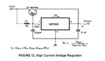
  1. Using an IC something like LT 1680 to provide boosting required.
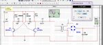
  2. To convert 9V DC to AC using astable multivibrator,use a step up-transformer & then rectify it.Not sure if it can operate at high currents.
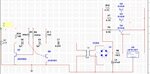
  3. To use a boost converter & use a PWM controller.

Of the three,to do simulation i don't think Multisim has such ICs in its data-base.
Second looks good,but can it work at high currents of 10 A.Even if it works is it efficient to do so ????
 

1) Perfectly fine solution
2) Okay solution if you don't need tight regulation. Also, you'd probably need a custom transformer.
3) Isn't this the same as 1)? (A boost converter IS a PWM controller)
 

Okay solution if you don't need tight regulation. Also, you'd probably need a custom transformer

A custom transformer ?????? aren't 9-18 V transformers commercial(Logical,who would be using such trans.)
Thought 2nd would be easier of all 3
 

A custom transformer ?????? aren't 9-18 V transformers commercial(Logical,who would be using such trans.)
Thought 2nd would be easier of all 3

You said you wanted 15V, not 18V. If you use a regulator on the output, then fine. But I don't think it will be as efficient or cost effective
 

Yes,it seems doing all that dc-ac-dc wouldn't be efficient
But why would the attached schematic not work.
Right now there is no regulator & as i already said about high currents,i may need to use a pass transistor around 7815
 

Attachments

  • Capture.JPG
    Capture.JPG
    142.4 KB · Views: 100

that will work, but not well. First of all, you've got NO control over output voltage. Secondly, your current is limited by your 2N3904 transistors; you're sure not going to be able to pump 10 amps through them for very long.
 

@barry: Yes,2N3904 seem to have max.continuous current of 200 mA,so replaced them with 2N3055 which have a max.continuous current of 15 A & also used a regulator 7815.The below schematic should be fine,right

But,then why doesn't the circuit seem to be not working in software.Is it the fault of a couple model files in software ????
 

Attachments

  • Capture.JPG
    Capture.JPG
    164.8 KB · Views: 106

The 78xx series of voltage regulators can only provide a maximum of 1/1.5 A load current.But i was talking about high currents.
Suppose we have 6 A at the o/p end before 78xx,the 78xx only allows 1A,the pass transistor allow the remaining 5 A to flow.Maybe i should use only 2 of those as a single BD 330 can allow 3A max..

attached is an image from dat-sheet of 78xx on how to do high-current regulation
 

Attachments

  • Captu.JPG
    Captu.JPG
    25.4 KB · Views: 80

The 78xx series of voltage regulators can only provide a maximum of 1/1.5 A load current.But i was talking about high currents.
Suppose we have 6 A at the o/p end before 78xx,the 78xx only allows 1A,the pass transistor allow the remaining 5 A to flow.Maybe i should use only 2 of those as a single BD 330 can allow 3A max..

attached is an image from dat-sheet of 78xx on how to do high-current regulation

Right. I was looking at that the wrong way. But, still, as Peter also points out, this is not an efficient design. Why do you object to using a boost convertor?
 

Yes,78xx series are generally not used in high current applications with high power dissipation.Maybe i should use it at 18 V instead. Aren't transformers with 1:1.5 turn ratio available????

About boost converter,i wanted to test my circuit first in software & then implement it.But usually Ics such as LT 1680 from post#1 or UC 3843 aren't available in software data-base.To simplify my task, usually spice model files of these are not available to create custom component.
I am also new to boost converter,but with the inefficiency of the above design i think i should go to those ICs.
 
Last edited:

Whaaaaaaaaaaaaaat? You're letting the fact that you can't simulate a circuit force you to use a poor, inefficient, expensive design? That's like the guy looking for his wallet under a street light even though he dropped it somewhere else, because "the light is better here."

And you most certainly CAN simulate an LT1680. Just go to the Linear website and download LTSpice.
 
  • Like
Reactions: tpetar

    tpetar

    Points: 2
    Helpful Answer Positive Rating
LOL!!!!
Right in post #1 i thought that this design would be inefficient due to repeated conversions,and i wanted to calculate efficiency.
If the efficiency turned out to be good,thought of using the design instead of buying IC as i could make do with the components i have,except that transformer.

Looks like i'll have to buy the IC afterall
 

@barry: Yes,I did simulate LT 1680 in LT Spice.But as my entire circuit is in Multisim,is there a way i can export this model from LT Spice to Multisim.

I found spice model of LT 1680 in a .sub file,which i am not able to open.Is there a way to open these .sub files ??? If i can access these spice models,i can use component wizard in Multisim to create custom component.

@Peter: In that circuit you were talking about in that article in Elecktor magazine,instead of UC 3843, UC 3842 should also work right ????
 
Last edited:

Status
Not open for further replies.

Part and Inventory Search

Welcome to EDABoard.com

Sponsor

Back
Top