Continue to Site

Welcome to EDAboard.com

Welcome to our site! EDAboard.com is an international Electronics Discussion Forum focused on EDA software, circuits, schematics, books, theory, papers, asic, pld, 8051, DSP, Network, RF, Analog Design, PCB, Service Manuals... and a whole lot more! To participate you need to register. Registration is free. Click here to register now.

PIC measuring voltage

Status
Not open for further replies.

78L05

Newbie level 4
Joined
Nov 20, 2009
Messages
7
Helped
0
Reputation
0
Reaction score
0
Trophy points
1,281
Location
zagreb
Activity points
1,336
Hello everybody, I have some problem and I hope you will help me to solve it.
I have power supply and resistor in the main line. Resistor is 0,47R and maximum current is 5A (DC), so, the maximum voltage drop on resistor is 5 * 0,47 = 2,35V. I want to measure current through resistor.
I would like to use PIC16F876A. I heard about TL431 and voltage reference on PIC (Vref+ i Vref-), but I'm not sure how it work and how I have to connect it.
BTW. For programming microcontrollers I use MicroCode Studio (PICBASIC Pro).

Thank you and best regards
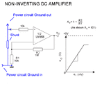
 

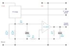
See example with LM385 :

shunt current amp.gif

Current_Sensing.jpg


Output from OpAmp goes to ADC pin of µC.

For measuring current, better use Hall sensor such as cheap ACS712, A1302,...


Best regards,
Peter
 

And, if I understood, if voltage on shunt is 2.35V LM358 (first schematic in your post) will "give" 5V at v0?
 

No, output voltage will be near 5V at full current.

Use smaller resistor value such as 0,1R. 0,47R have big impact on circuit, but all depends what you want to achieve.
 

When current is maximum (5A) voltage drop across shunt is 5*0,47 = 2,35V, that is full curent.
What I want to achieve is to have 5V for microcontroller when the current is maximum (5A), although voltage drop on shunt is just 2,35V.
 

Yes, that is scenario.

Like i says earlier on OpAmp output you will get near 5V for ADC when you have full current throught shunt resistor.

Just make appropriate resistor calculation for R1 and R2.
 
  • Like
Reactions: 78L05

    78L05

    Points: 2
    Helpful Answer Positive Rating
I assemble schematic () in ISIS (Proteus) and one thing confuse me.
I can't get voltage more than 4.00V at output. Amplifier works, but when LM358 should give 5V at output it gives 4.00V as maximum.
On the schematic (picture above) there is graph which shows that 4V is amplitude, so, what I am doing wrong?
I measure voltage between pin 1 of LM358 and GND (ground).
Thanks!
 

The max output of the LM358 is around Vs-1.5V, so you probably have Vs as 5V

This looks like you are trying to monitor the current in a motor driver.

Change the 0,47 ohm to 0.1 ohm , 5A = 0.5V so you will need an amplifier with
a gain of 10. Change the LM358 to a RRIO opamp (rail-rail input output) with its
supply voltage set the the same as the PIC.

Using an amplifier to increase the signal into the PIC will give you maximum resolution,
but if you can live with less resolution run the 0.5V directly into the A/D input on the PIC.

bit resolution with amp = 5A/1024 ~ 5mA, resolution with direct connection ~ 50mA

You can put a voltage divider on the 5V to get 0.5V and put that into the Vref+ and get
full resolution, but it will be noisier and you will have to configure the ADCON register
bits for Vref+ and Vref-.
 
Last edited:

Status
Not open for further replies.

Similar threads

Part and Inventory Search

Welcome to EDABoard.com

Sponsor

Back
Top