Continue to Site

Welcome to EDAboard.com

Welcome to our site! EDAboard.com is an international Electronics Discussion Forum focused on EDA software, circuits, schematics, books, theory, papers, asic, pld, 8051, DSP, Network, RF, Analog Design, PCB, Service Manuals... and a whole lot more! To participate you need to register. Registration is free. Click here to register now.

[SOLVED] 900 W DC/DC Full Bridge Converter

Status
Not open for further replies.

andrew06

Newbie level 4
Joined
Sep 29, 2010
Messages
5
Helped
0
Reputation
0
Reaction score
0
Trophy points
1,281
Activity points
1,325
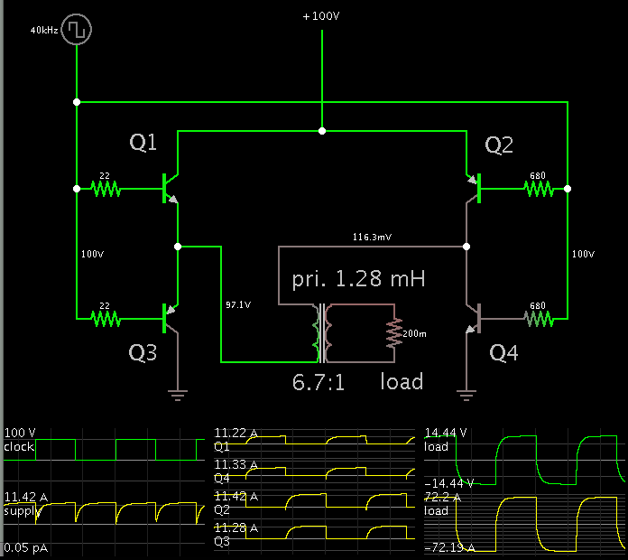
I am designing a 100 VDC to 14 volts VDC isolated converter, 70 Amps output.
I will use a full bridge, with one single winding also on secondary side.
Max Duty cycle is 0.45
Core is a TX58 toroid with Al= 2100 nH per turn and Surface= 152 mm²
Bsat=0.15 T
PWM frequency is 40 KHz generated by a good old TL494 (Ct= 1nf Rt= 14K)

I did a preliminary calc to know the primary number of turns:

Nprimary= (Primary voltage * Duty *1000000) /(2* Frequency *Bmax * Surface)
Nprimary= 24.7 turns

Assuming a 1.4 voltage drop on the secondary rectifier, Turns ratio should be close to 100/(14 + 1.4)= 6.5

The Primary current drawn should be close to 70*14/100= 9.8 Amps

Now, the problem come when I calculate the inductance of the primary winding

Lp= Np turns x Np turns x Al
Lp= 24.7 x 24.7 x 2.1= 1281 uH

1281 uH at 40 KHz is quite a big impedance and my SMPS may not work :
So, I did not understood how to deal with this.
I have tried many variations with changing frequency, forcing number of turns, changing also core / material without proper results.

Any help should be really appreciated

Kangoo
 

The value that you calculated is the magnetizing inductance. Higher this value is and better the transformer is.
You could increase the value of B from 0.15T to 0,2T without problem for the saturation of the core. For instance the material 3C90 could work at 0.25T @100°C without problem.
If you use a higher B, you can decrease the number of turns.

Stefano
 

The value that you calculated is the magnetizing inductance. Higher this value is and better the transformer is.

Thanks Stefano. The problem comes with LTspice simulation of the transformer.
The LTspice model I have needs to know L_primary, L_secondary and Turn_ratio. I have used the L values calculated with the formula giving the magnetizing inductance.
Is there any other formula to use for a better calculation of primary and/or secondary inductance ?

Cheers
 

A simulation shows that your values ought to work.


It was done in Falstad's simulator. It has specs for (a) inductance of the primary winding, (b) ratio, and (c) coupling coefficient.

I used transistors instead of mosfets, because the mosfet model did not appear to develop sufficiently low 'On' resistance.
 

Thanks BradTheRat. This simulator looks very interesting !
 

Thanks Stefano. The problem comes with LTspice simulation of the transformer.
The LTspice model I have needs to know L_primary, L_secondary and Turn_ratio. I have used the L values calculated with the formula giving the magnetizing inductance.
Is there any other formula to use for a better calculation of primary and/or secondary inductance ?

Cheers

I don't think that the primary inductance is a problem using LTspice as simulator, You can fin in attachment a very simple full bridge converter that use a simple model of linear transformer.
LTspice is a good simulator but when I simulate a power circuit I prefer Psim.
Psim is not free as LTspice but there is a free limited version of Psim that can be used for educational purpose. Psim is very very fast respect to spice.
In a full bridge converter is very important to add in the transformer model the leakage inductance, because this inductance "eats" duty cycle of the converter. The leakage inductance is very difficult to calculate but is very easy to measure.

Stefano
 

Attachments

  • fb_01.zip
    1.7 KB · Views: 208

Thanks Stefano.

I have run your LTspice model. Does it means that L3 is the leakage inductance ?
4212182000_1363721249.jpg


Andrew
 

Thanks Stefano.

I have run your LTspice model. Does it means that L3 is the leakage inductance ?
4212182000_1363721249.jpg


Andrew

Yes L3 is the leakage inductance seen at primary side. To measure this value you need to short circuit the secondary of the transformer and measure the inductance at primary. The value of L3 could be higher, this value depend on the transformer construction.

Stefano
 

Hi,
I also want to simulate fullbridge DC DC converter with the following parameters in LT spice with 95% efficiency. Here the problem is how to find the transformer specifictions like leakage inductance and inductance and restance of primary and secondary with out using core. can any one provide me the formulas to find these parameters? if you provide me the spice model for this i would be thank full.
my specifications are:
i/p vol - 400v
o/p voltage - 28v
o/p power - 3kw
Frequency - 1mhz
 

Hi Romeo,

I have found a great tool that may help you:

**broken link removed**

I am now using it for a new battery charger project.

Andrew
 

Hi,
Thank you for reply andrew that tool looks interesting but my frequency is 1mghz but in this tool i can give only up to 300hz..

can any one tell me how can i do softswitching(ZVS) in fullbridge converter? i have attached my LTspice file here but Iam doing hard switching here. can any one change the mosfet timings and Transformer specifications to get 28volts output with 3kw power

my specifications are:
i/p vol - 400v
o/p voltage - 28v
o/p power - 3kw
Frequency - 1mhz
 

Attachments

  • freq testing proj.zip
    1.5 KB · Views: 175

can any one change the mosfet timings and Transformer specifications to get 28volts output with 3kw power

my specifications are:
i/p vol - 400v
o/p voltage - 28v
o/p power - 3kw
Frequency - 1mhz

Just to give some answer (even though mine is not the most expert)...

If we assume square waves...

The primary will carry 8.5 A average.
The secondary 108 A.
Turns ratio 13.5:1. (yields 29.3 V)

After simulating with a range of primary values (with a 0.27 ohm load, and a 2.7 ohm load), it looks as though the primary should be between 100 and 200 uH.
Below that and the waveforms start looking spikey .
Above that and the output waveform takes several nanoseconds to ramp up to peak.

You may intend to run sine waves through it, however. That will change the specs.

I can't advise much about ZVS. A search of this message board will turn up discussions on that topic.
 

Thank you for reply!

I have tried with these specifications in LTspice but I am getting only 53%efficiency what parameters can i change in this ckt to get 90% efficiency?
I am trying to do synchronous rectification with phase shifted Fullbridge converter with above specification. please find image of my ckt.

Thanks in advance

https://obrazki.elektroda.pl/7185609900_1369093940.jpg
 

I am trying to do synchronous rectification with phase shifted Fullbridge converter with above specification. please find image of my ckt.

Now I notice the LC series arrangement. It creates resonant action through the transformer, thus turning square waves into sine waves. Transitions at 0V.

There are a few things that must be right, in order to extract maximum efficiency.

1.

The mosfets/transistors need to be biased sufficiently to turn on and conduct sufficient current.

Since you have put N-mosfets at the high side (more positive polarity), you need to apply a higher volt level to the gate, in order to turn it on. This is because the gate is referenced to the source (more negative( terminal, and it is more easily done when the source has a definite path to ground.

An alternate method you can use, is to put P-mosfets at the high side. Then you must apply 400V in order to turn them off.

2.

Your C2 and L5 values need to be tailored to the load. My simulation shows approximately what you are aiming for.

I used 150 uH for the transformer (per my post #12).
Then in order to obtain something that approximates sine waves, I found it necessary to increase your C2 and L5 values.

Screenshot:


3.

Your output stage has mosfets in the role of switches. The same principle in item #1 also applies to them.

To help along the design effort, try using diodes for the time being.
 

hej thank you for reply,
I have tried to simulate the model in Lt spice with the above mentioned parameters to get 95% efficiency but Iam not able to get that. can any one tell me how can i choose the transformer primary and secondary resistance and leakage inducatance of transfomer to get these efficiency of 95%, here Iam atatching the ltspice model which is operated in phase shift resonant synchronous rectification please make the changes in it?
Thanks in advance
 

Attachments

  • synchronous rectifb.zip
    1.7 KB · Views: 168

Status
Not open for further replies.

Similar threads

Part and Inventory Search

Welcome to EDABoard.com

Sponsor

Back
Top