Vermes
Advanced Member level 4
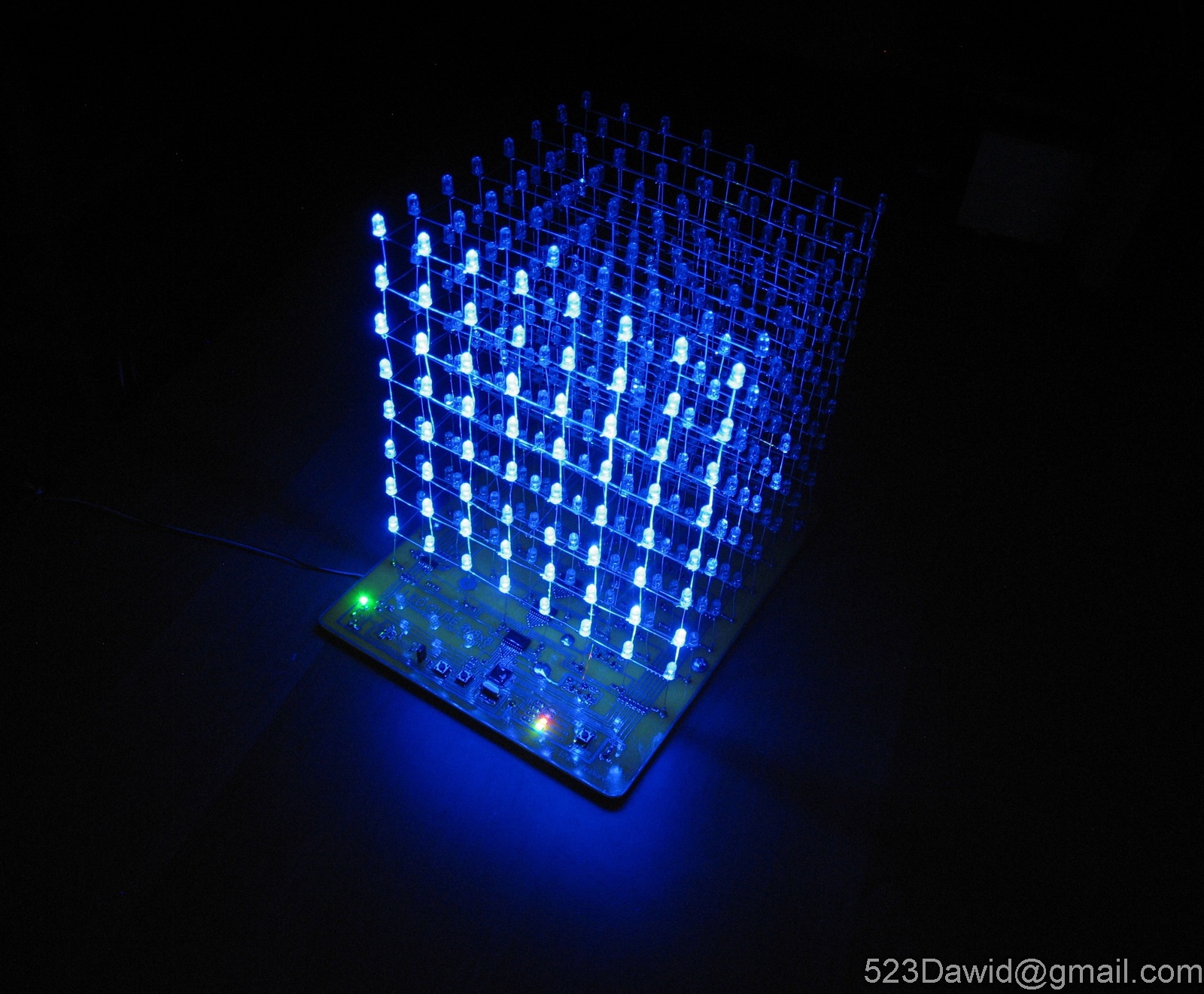
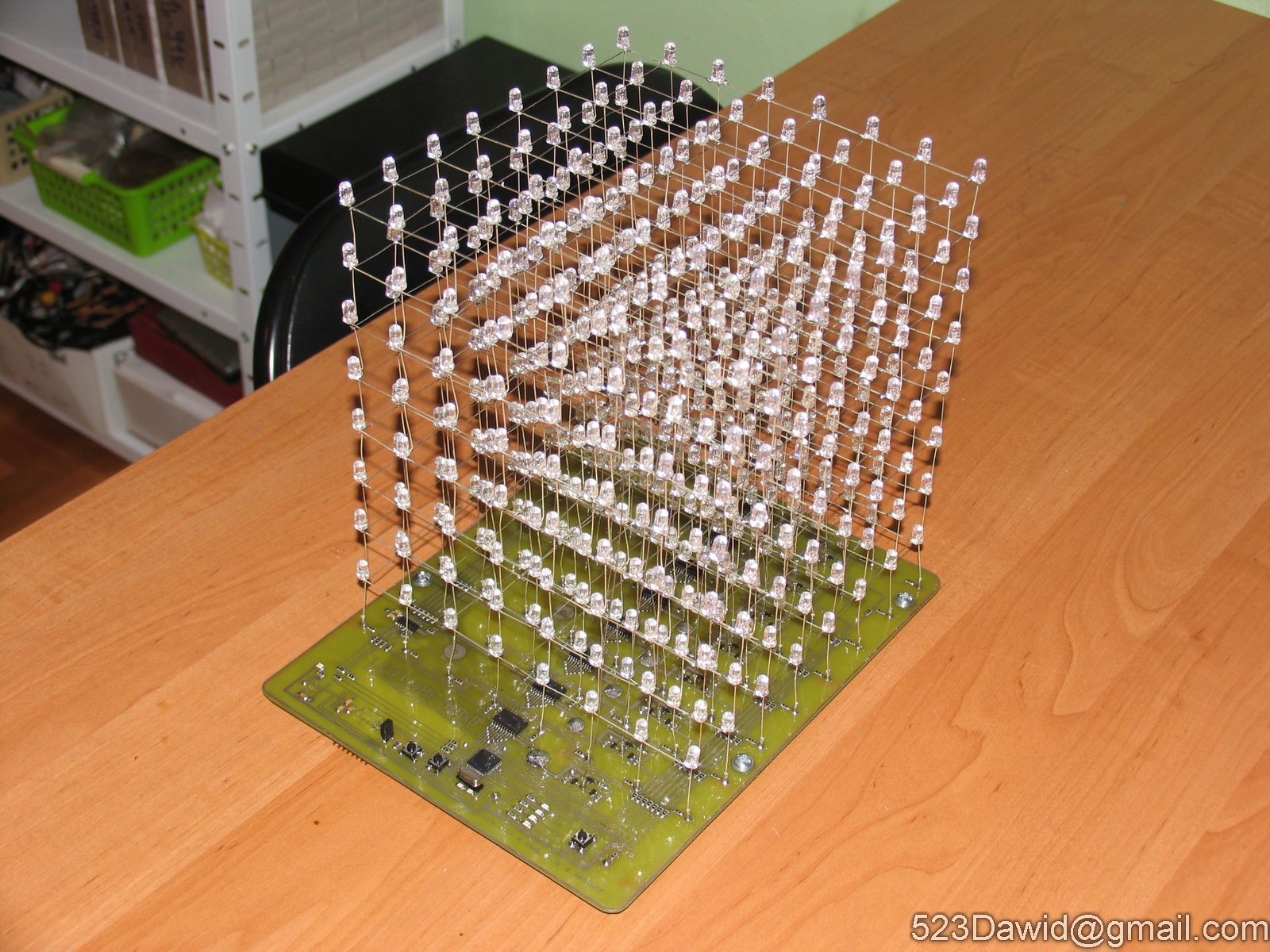
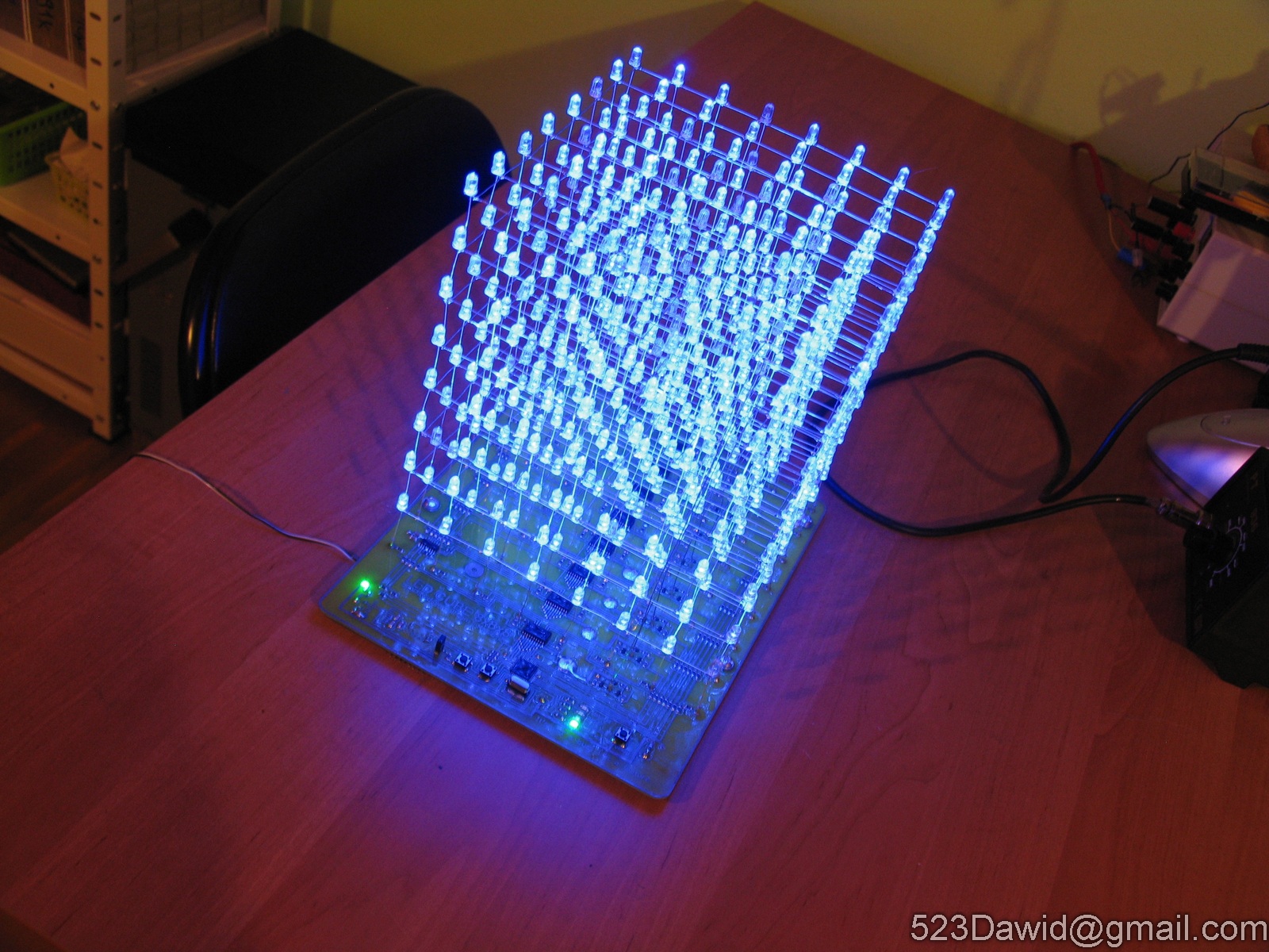
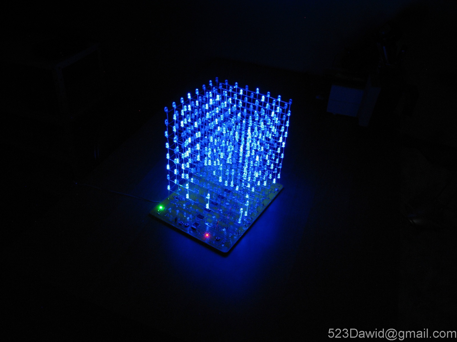
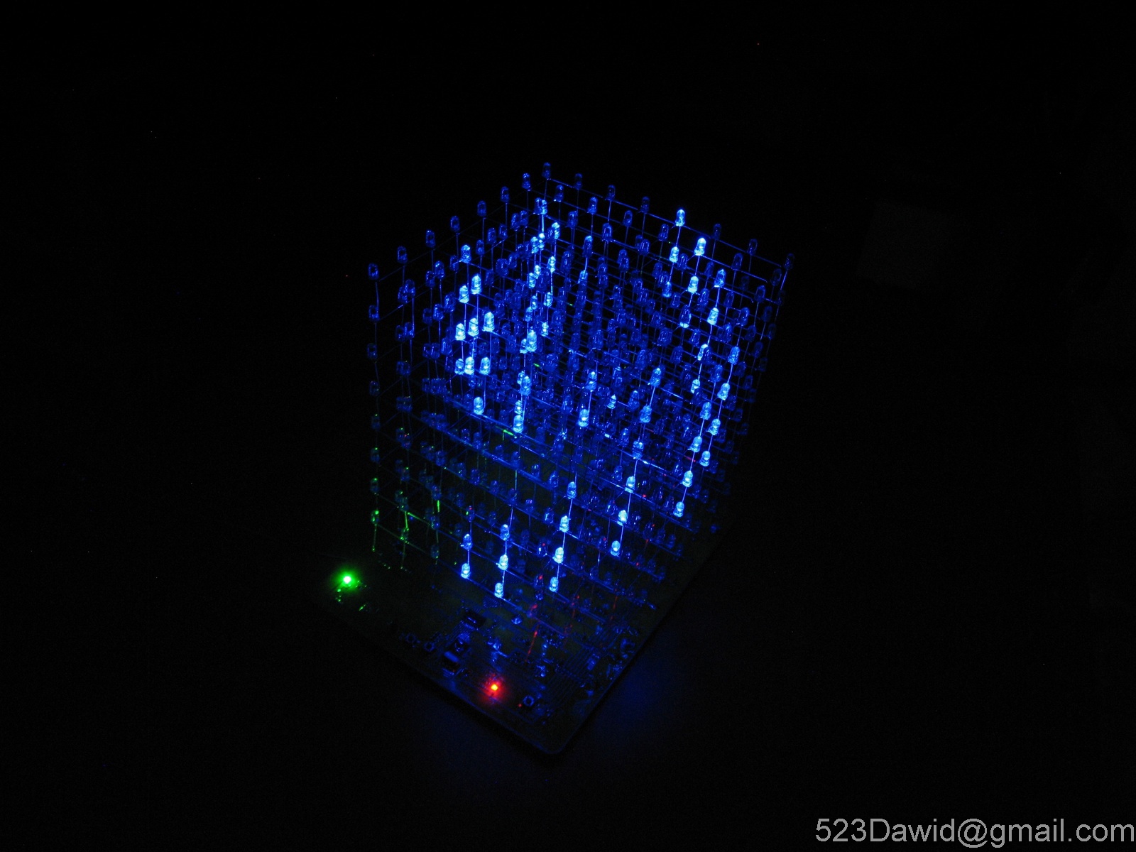
It is a light decoration in form of a LED Cube 8x8x8. It uses blue LEDs and processor Atmega16. Although the design was inspired by another similar construction which can be found at instructables.com, some modifications were made to improve its operation.
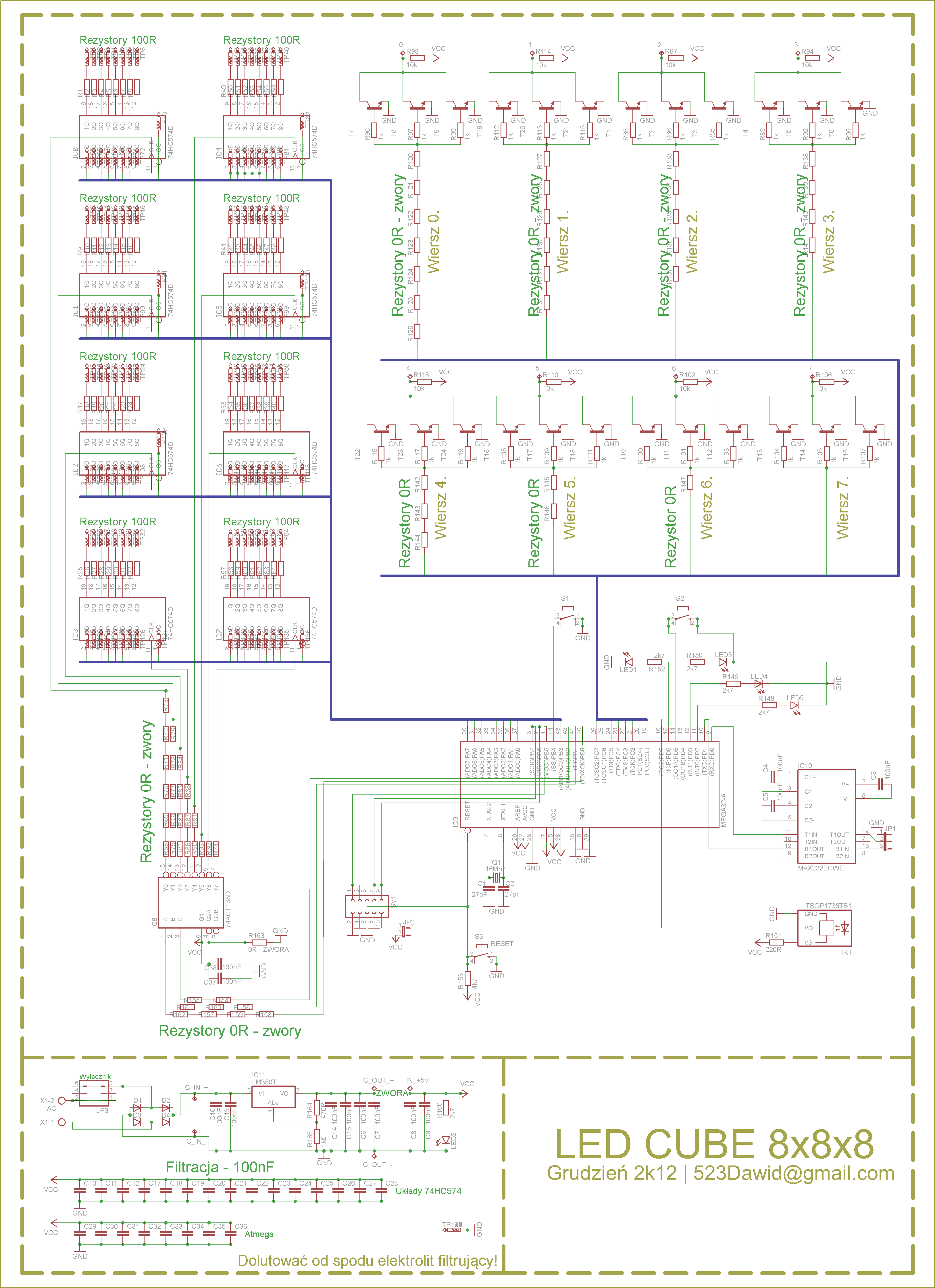
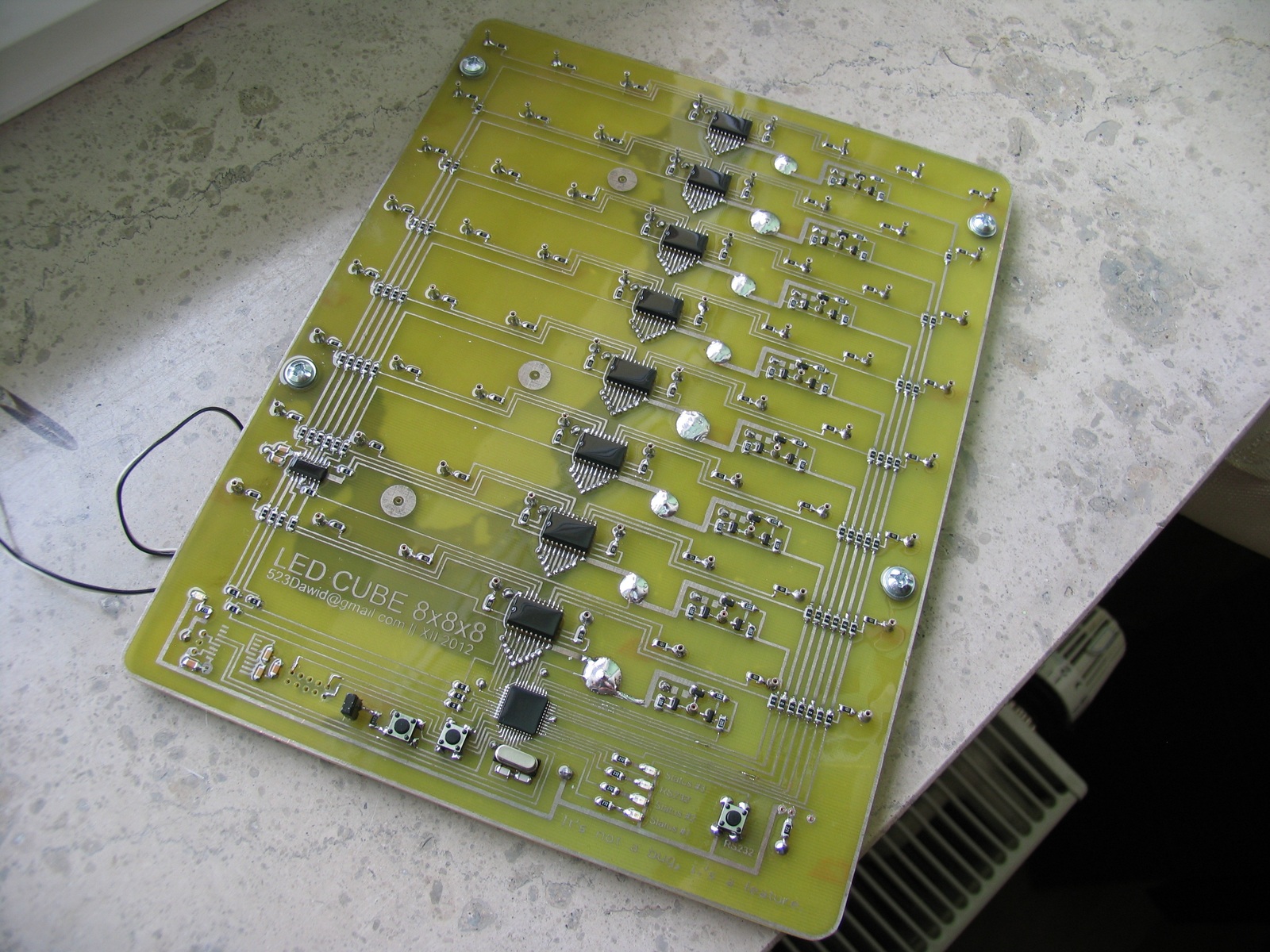
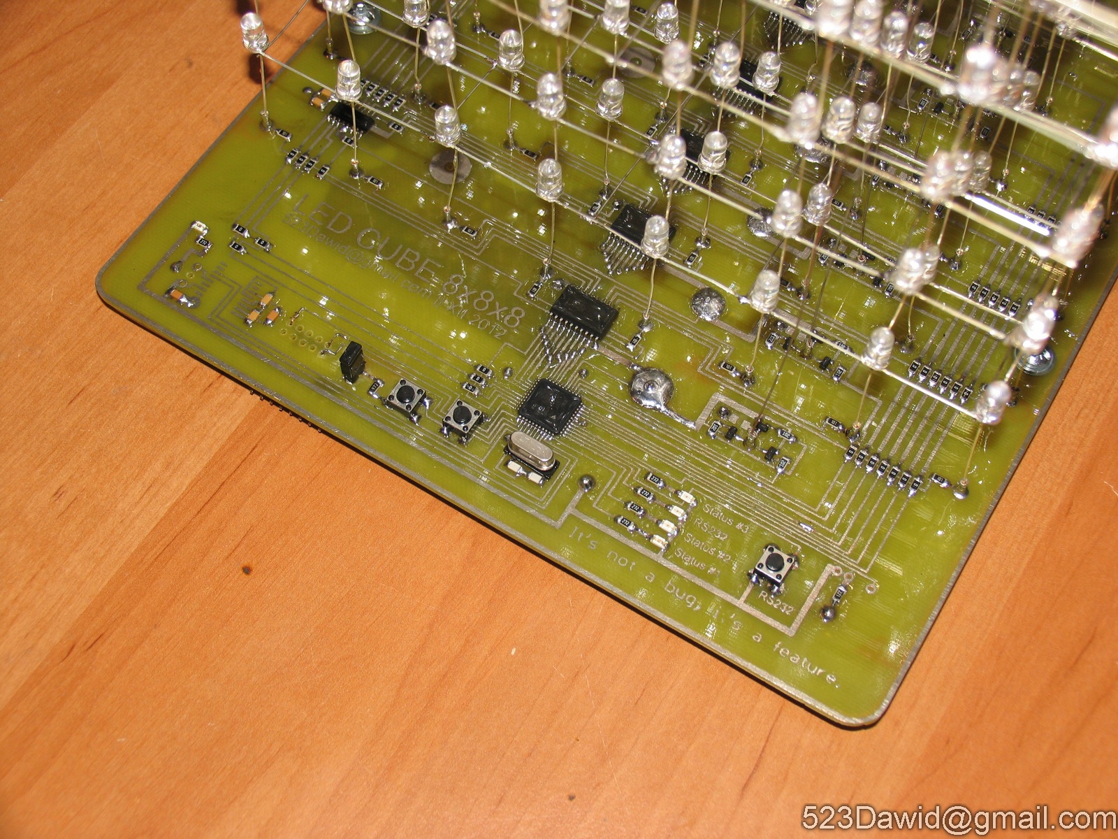
Processor Atmega16 is clocked by an external crystal quartz. Levels are selected by transistor keys (3 transistors). The levels are controlled by a demultiplexer 74138 that selects the register by controlling the clock connector. Additionally the original design assumed using MAX232 for communication, but it was not mounted in this project. Receiver TSOP1736 was applied.
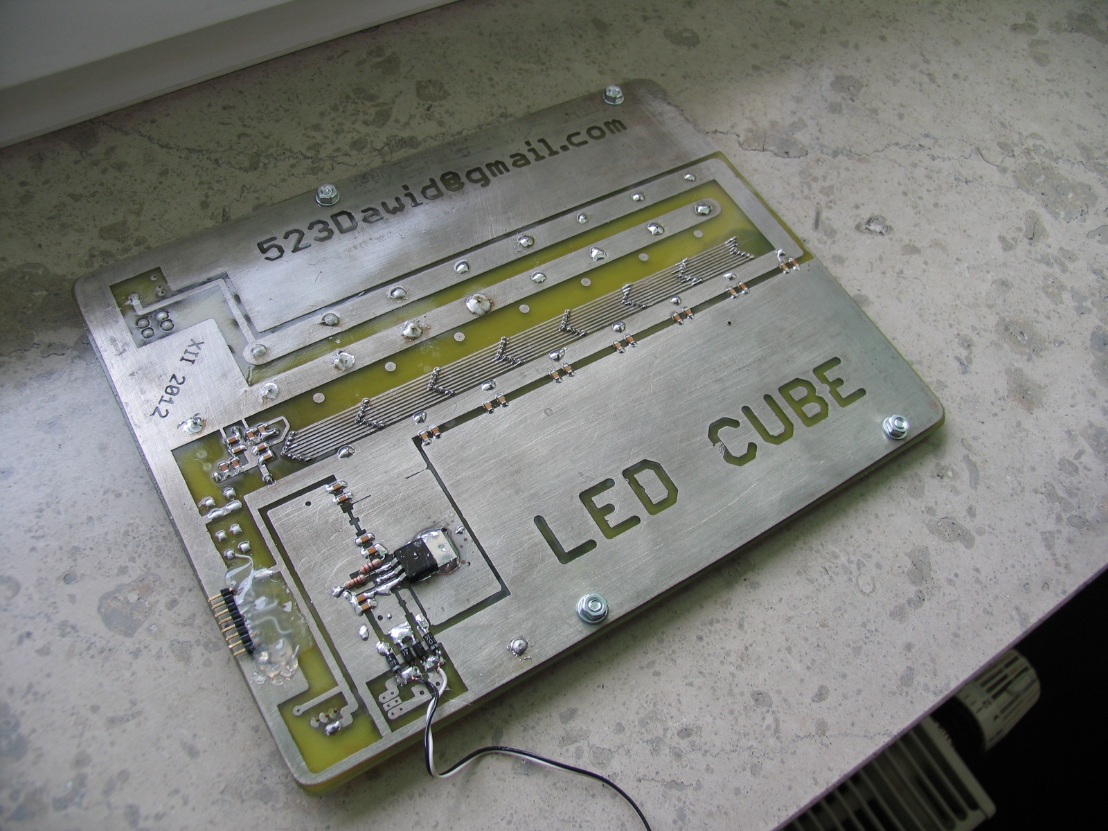
The double-sided PCB was designed in Eagle. The upper part includes the entire logic and the bottom part has the bus that connects systems 74HC574 with the microprocessor and power supply with filtering capacitors. The remaining part of the PCB can be, depending on your needs, the ground or plus of power supply. Space for the ISP connector is on the top side of the board. Although, if you do not remember to add bushings from the top to the bottom, it is difficult to solder them under the plastic and thus you have to move the connector to the bottom side. In the design which can be found on the original thread (attachment) it is taken on board and the connector is soldered on the bottom side.
The device uses the original program without modifications.
Pictures:
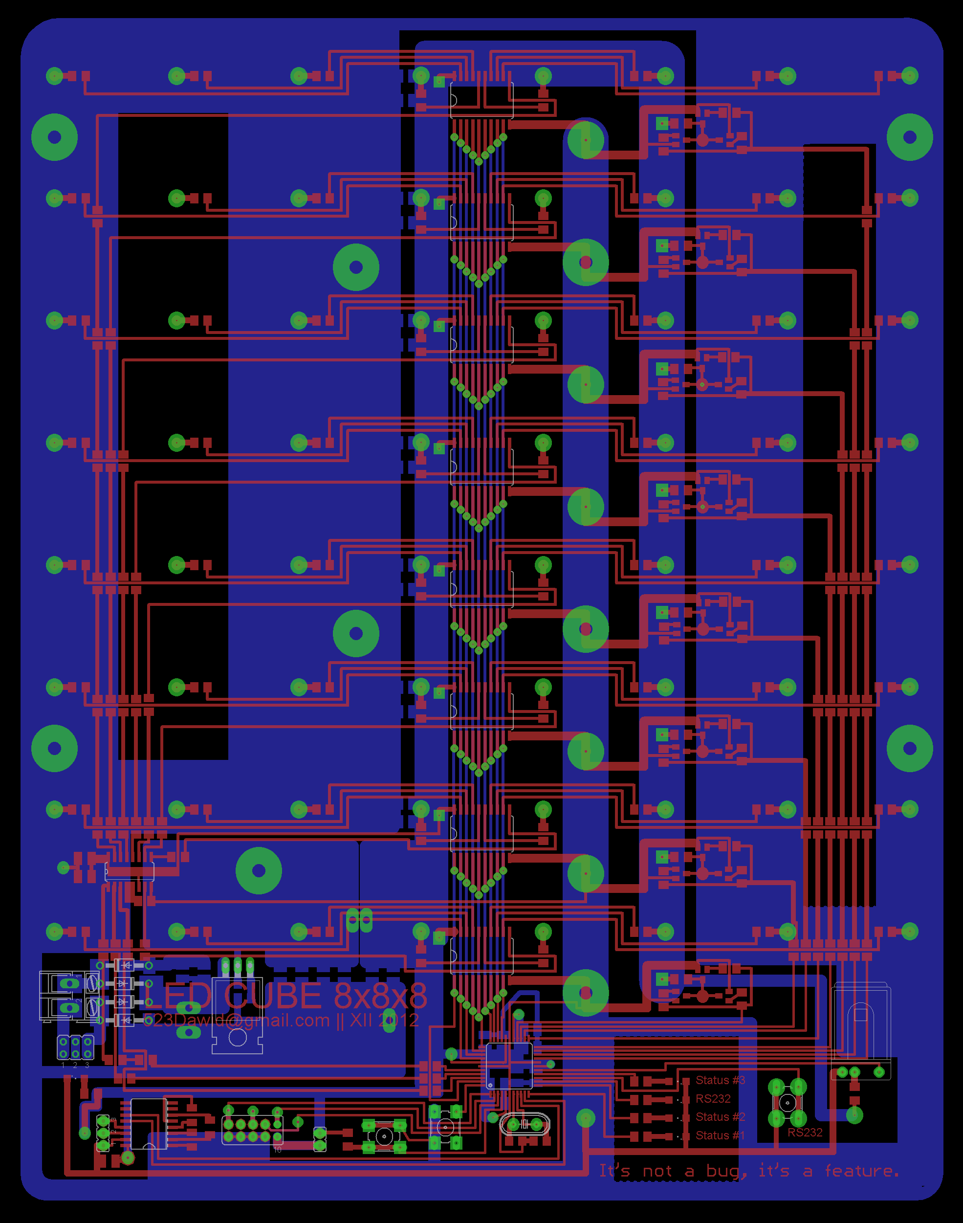
The PCB is both driver and base of the construction, so that it was performed of two separate one-sided laminates, instead of one two-sided. That ensures the perfect rigidity of the whole construction.
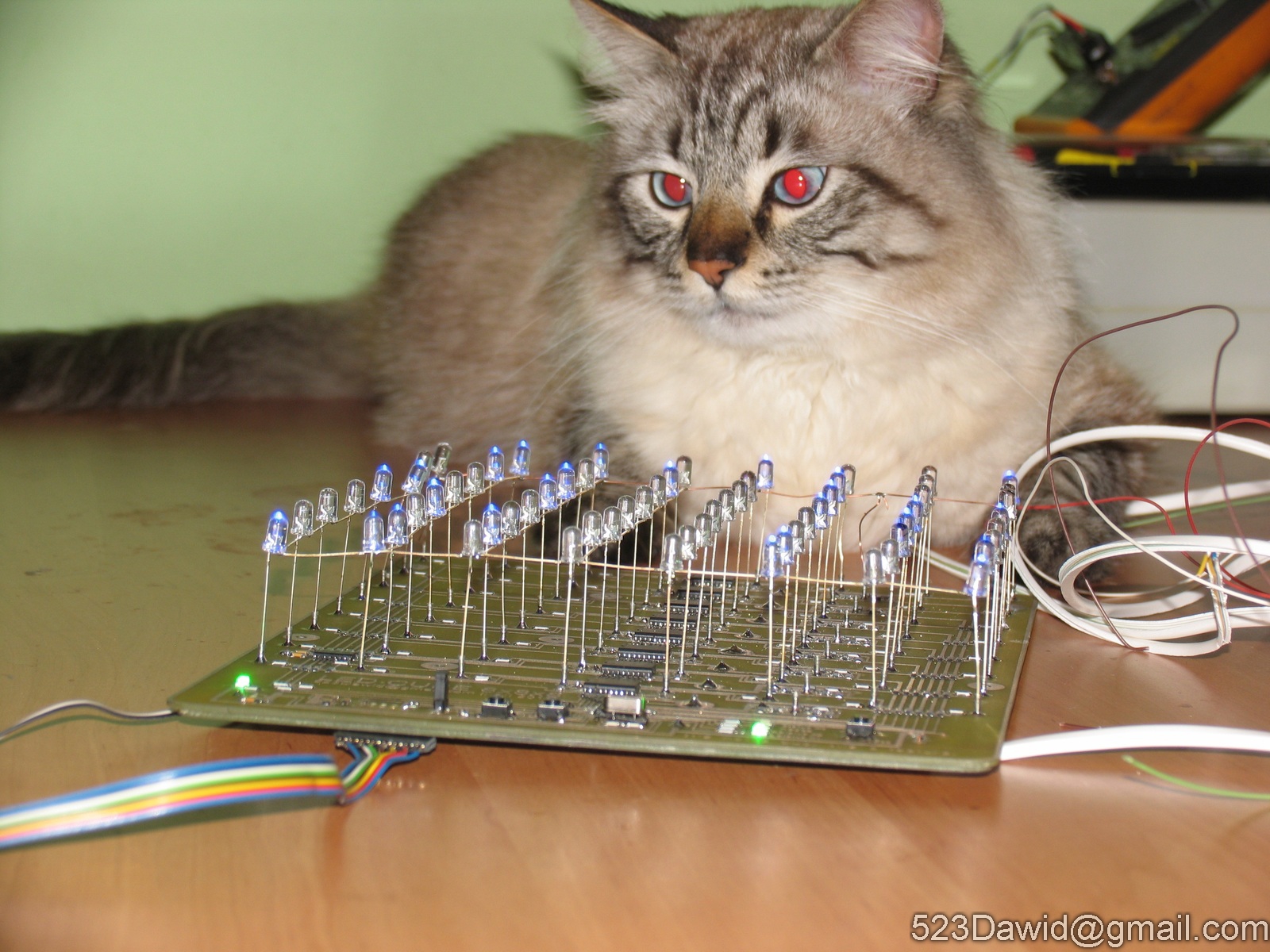
PCB was made in thermal transfer method, then covered with tin. The whole, after mounting the components, was painted with a transparent lacquer and it looks nice.
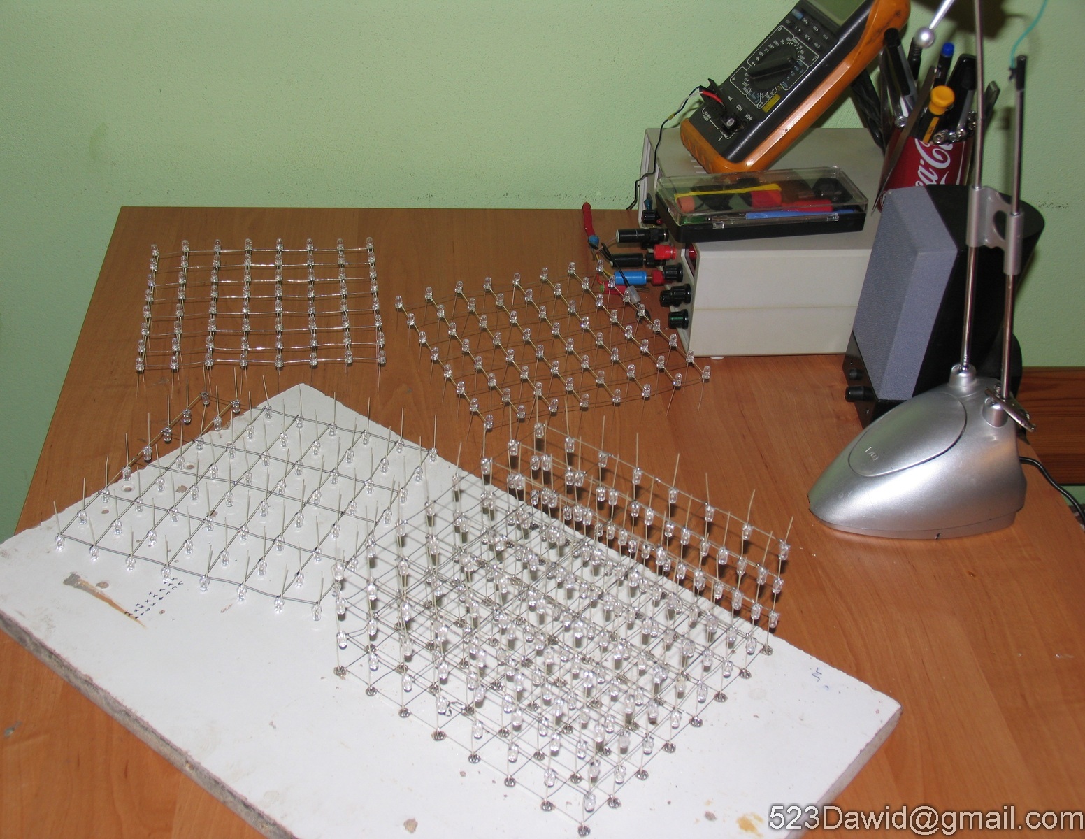
It is better to use 3mm LEDs than 5mm, because they are too big and it is hard to maintain the horizontal line.
The whole construction is not soldered to the PCB, single pins are derived from precision bases. It is very stable and can be put upside-down.


Link to original thread (useful attachment) - Led Cube 8x8x8 @Atmega16