Continue to Site

Welcome to EDAboard.com

Welcome to our site! EDAboard.com is an international Electronics Discussion Forum focused on EDA software, circuits, schematics, books, theory, papers, asic, pld, 8051, DSP, Network, RF, Analog Design, PCB, Service Manuals... and a whole lot more! To participate you need to register. Registration is free. Click here to register now.

why power supply has no effect in proteus

Status
Not open for further replies.

100k

Member level 1
Joined
Jun 16, 2012
Messages
37
Helped
1
Reputation
2
Reaction score
1
Trophy points
1,288
Activity points
1,607
HI
I am using proteus for my simulation. It automatically assume that the supply is given to a given IC/Uc. How to disable this action? I want the simulations to be very real. Please suggest where are the settings for disabling this. Also, how to alter the convergence parameters in proteus?
 

In practice, all simulations make assumptions. In fact, the simulated component files may not have simulation behavior encoded for what should occur if there is no power connected to the IC.
Thus, the simulation will not be improved.
If the developers of each simulated component were to implement a very complete simulation, it may take a very long time to develop, and it would be very huge, and a large percentage of that
simulation would never get executed by users, so in a way it would be a wasteful thing for developers to do.
Much like an video console driving simulation will never be like the real thing (for example the accurate simulation would be for the software to simulate the car insurance paperwork and waiting days for the simulated documents to arrive, before it will let you continue with the game). Even if the simulation did allow this, 99% of players would not be interested, and therefore it is a waste of a developer's time to implement this for the 1%.

Having said all that, personally I think the software should enforce power supply connections just as a symbolic gesture, before allowing the simulation. It wouldn't necessarily improve the simulation, but it would encourage people to draw complete circuit diagrams than the mess that some people draw.
 

I guess it depends on the device you refer to.
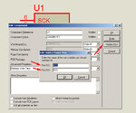
If the device has hidden pins then using the properties of the device you can connect them to a different net if you wish
proteus_hidden_pins.jpg

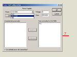
The voltages of the power rails can be viewed or changes from design -> configure power rails
proteus_power_rail.jpg
 

I was working with NE555 ic, it didn't show any hidden pin like that.
I want those Vcc and Gnd pins to have effect in my simulation
 

The device you describe has a Vcc and GND pin and depending on the voltage you connect there you get output pulses of different amplitude (voltage) so I'm not sure what you mean when you say that "Vcc and Gnd pins have no effect in my simulation"
 

I mean to say that the device ne555 works properly even tough the Vcc and Gnd pins are not connected. I want the NE555 to stop showing any pulse if there is no supply connected to it. Help me to achieve this.
 

If you leave the Vcc pin unconnected to a source then it is considered to be connected to the Vcc net (5v) so if you want something different then connect it to a source and set it to the voltage you want or connect a ground to it.

What sky_123 said stands, the 555 is just a simplified simulation model so you can't expect to have the same behaviour as the read device, just the basic functionality , for example the simulation model will work even with a power supply of 0.5v while the real one will not.
 

Status
Not open for further replies.

Part and Inventory Search

Welcome to EDABoard.com

Sponsor

Back
Top