Continue to Site

Welcome to EDAboard.com

Welcome to our site! EDAboard.com is an international Electronics Discussion Forum focused on EDA software, circuits, schematics, books, theory, papers, asic, pld, 8051, DSP, Network, RF, Analog Design, PCB, Service Manuals... and a whole lot more! To participate you need to register. Registration is free. Click here to register now.

Counting Negative Pulses with PIC16F877 Timer0

Status
Not open for further replies.

alibataineh

Newbie level 2
Joined
Dec 17, 2012
Messages
2
Helped
0
Reputation
0
Reaction score
0
Trophy points
1,281
Activity points
1,298
Hello everyone,
Hope you're doing well .
I study power engineering and this is my third year. To be able to graduate I have to pass micro-controller course, even though it's not related to my field of study.
Anyway, I was searching online and I'm really thrilled to find this site.
I need your help regarding programming TMR0 as counter. Does anyone know how to write a program to count the number of negative pulses received on one of the PIC 6F877 I/O pins ?

This code actually counts the positive pulses :

main:

; 1. configure tmr0
Code:
movlw b’10111000’
movwf option_reg
; 2. Set up ports
Code:
movlw 0x00 ;
Movwf trisd
movlw B’00011111’ ;
Movwf trisa ;
; 3. Mask 2nd digit of TMR0
Code:
loop:movf trm0,w ;
Andlw 0x0f;
call segment
movwf portd ;
goto loop ;


What about the negative pulses ?


Thank you in advanced,
You'd really save my life if you know the code
Peace
 
Last edited by a moderator:
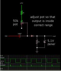
Can't help much with the code for your pic.

However in case it must not be exposed to negative volt levels...

you will need to convert the negative pulses to a positive polarity.

A simple circuit below can deliver a positive pulse at the end of the negative pulse.

Screenshot:


The simulation shows the pot adjusted to 32k ohms.

The upper resistance must be sufficient ohms so that the output never goes above or below a safe volt level for your device.

The 5.1V zener is optional although a good idea.
 

    V

    Points: 2
    Helpful Answer Positive Rating
Thank you so much sir!I really appreciate your reply .
Although, My teacher insists that there is a way to solve the circuit with a code without converting the negative pulses .
But really thank you so much :)
 

As stated, if you put a negative voltage on the PIC input it will be damaged. The silicon structure of the PIC is not rated to withstand negative voltages beyond what it's static protection diodes can handle and that isn't very much.

Does your teacher really mean the pulses are of negative voltage, going below ground potential, or do they mean negative going edges? A negative going edge is one where a high logic level drops to a low level, the PIC does have a feature for detecting that and using it to control TMR0, otherwise you need extra components.

Brian.
 

Hi,

Think you need to clarify what you mean by 'Negative pulses'.

Brad has shown a circuit for converting pulses from a negative voltage source which, if fed directly without the circuit Brad shows, will damage the Pic.

I suspect you actually mean the Negative transistion of a pulse, the fall from high to low ?

Your current code increases timer0 on the Positve transision of the pulses, if you see the datasheet for the Option Register you will see what you need to do to make it count on the Negative transisions
 

Status
Not open for further replies.

Similar threads

Part and Inventory Search

Welcome to EDABoard.com

Sponsor

Back
Top