rakesh1987
Junior Member level 3
Rising edge of pulse and falling edge of pulse should be determined separately using CMOS IC ?
Follow along with the video below to see how to install our site as a web app on your home screen.
Note: This feature may not be available in some browsers.
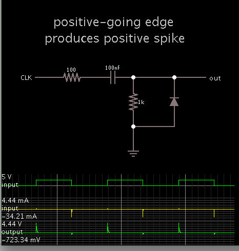
If you want a short pulse on both the rising and falling edge of a pulse you can use an XOR gate. Connect the signal directly to one of the XOR input pins. Also connect the signal through a series resistance and capacitor to ground to the other input. The XOR will generate a positive pulse at both the rising and falling edges with a width approximately equal to RC.
Not quite. The XOR circuit I described generates a positive pulse for both the leading and trailing edges of the pulse.Add this circuit to each comparator, post #2.
I believe this is similar to what Crutschow described, post #3.
Not quite. The XOR circuit I described generates a positive pulse for both the leading and trailing edges of the pulse.
To use this circuit to catch the negative edge you would invert the diode polarity and replace the ground to the resistor and diode with the plus supply voltage. If you still want a positive pulse from that then you could run this signal through a Schmidt-trigger logic inverter such as the CD40106.
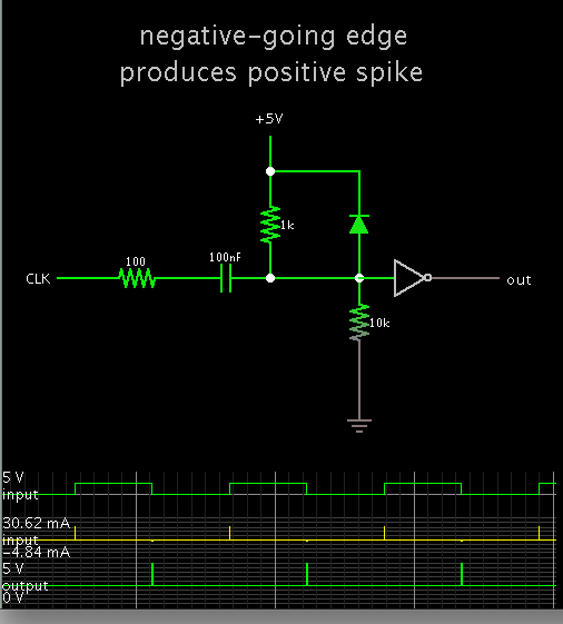
The circuit looks OK but the 10k ohm resistor to ground is not needed.
The connection to ground is through the resistor and the +5V supply. Also the inverter has a connection to ground. So there are plenty of ground connections, they just are invisible on your schematic.I agree, I only added it to show how the circuit is referenced to ground.
It didn't look right without a connection to ground somewhere.
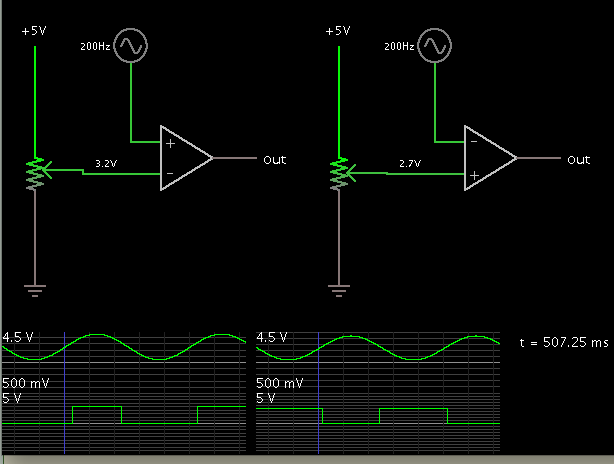
That appears to be a level detector, not an edge detector.