meysam_abbasinia
Advanced Member level 4
hi friends
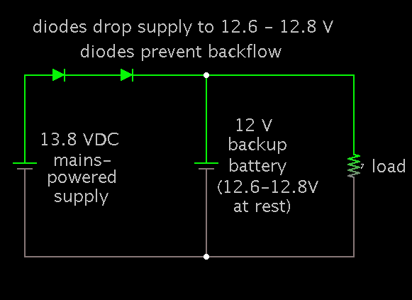
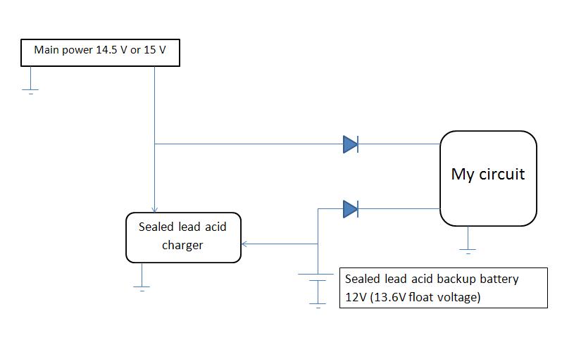
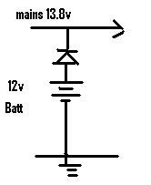
I design a circuit that need work with main power and backup battery, when main power disconnected i need backup battery supply my circuit automatically. my battery is 12V and main power is 13.8V and i need when return main power battery charging started and after raise it's voltage to 12V battery charge stop.
my battery is Sealed Lead Acid.
thank you.