Continue to Site

Welcome to EDAboard.com

Welcome to our site! EDAboard.com is an international Electronics Discussion Forum focused on EDA software, circuits, schematics, books, theory, papers, asic, pld, 8051, DSP, Network, RF, Analog Design, PCB, Service Manuals... and a whole lot more! To participate you need to register. Registration is free. Click here to register now.

pulse charging to a capacitor

Status
Not open for further replies.

capacitor1

Member level 3
Joined
Jul 25, 2012
Messages
66
Helped
0
Reputation
0
Reaction score
0
Trophy points
1,286
Activity points
1,744
Hi All,

In the attachment you may find the pulse waveform I would like to charge to a capacitor.


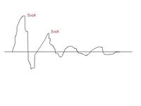
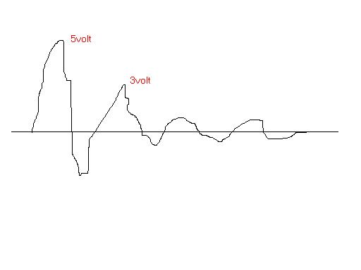
I have tried a bridge with a capacitor to store this pulse but it seems that only the energy ofhalf of the first positive pulse has been stored.Is there any way I could store all of its energy in the cap?

Regards,
Capacitor1
 

Not sure what you are trying to do. An active rectifier will do what you want. If it's some sort of energy harvesting , then active rectification
won't be the correct answer. Using schottky diodes would also help , but you will still lose some voltage in the bridge.
 

can you specify the max voltage of the cap

also post the max signal voltage

i think that the signal voltage is more than that of the capacitor voltage
 

You are apparently assuming an ideal voltage source supplying the waveform. That's completely unrealistic because it would involve infinite energy. A real energy source has an impedance. It must be known to design an energy harvesting circuit.
 

Not sure what you are trying to do. An active rectifier will do what you want. If it's some sort of energy harvesting , then active rectification
won't be the correct answer. Using schottky diodes would also help , but you will still lose some voltage in the bridge.

I used schottky dioded in the bridge but my problem is that the first pulse rises to 5 volts and the other pulses are less than that. So when ever the first pulse is charged( or half of it to be precise) the other pulses will notener be able to charge the cap anymore since they have less voltage than the cap has.

So how could I make my circuit benefit from all the energy in all the pulses?

- - - Updated - - -

can you specify the max voltage of the cap

also post the max signal voltage

i think that the signal voltage is more than that of the capacitor voltage

the signal max voltage is 5 volts and the cap I am using is rated 25 volts

- - - Updated - - -

You are apparently assuming an ideal voltage source supplying the waveform. That's completely unrealistic because it would involve infinite energy. A real energy source has an impedance. It must be known to design an energy harvesting circuit.

This pulse is generated from a coil so I really don't know what the output impedance is? suppose I know it how can I charge all the energy?
 

I think the fact that the capacitor has not discharged enough after the first pulse that the second pulse has no effect means your cct is getting all the power it needs.
No point in trying to add more power to the cap , it has enough. Or I'm missing the point :0)
Another option is some sort of switch to switch in another cap after the first has been charged , storing the second pulses energy on a second cap.
 

I think the fact that the capacitor has not discharged enough after the first pulse that the second pulse has no effect means your cct is getting all the power it needs.
No point in trying to add more power to the cap , it has enough. Or I'm missing the point :0)
Another option is some sort of switch to switch in another cap after th e first has been charged , storing the second pulses energy on a second cap.

When the cap charges to the voltage of the first positive pulse which has the max peak voltage the second pulses will discharge the cap since they have a lesser voltage than the first pulse.

Is there any switch circuit I could use to charge another cap or is there anyway to add the energy of the other pulses to the first?
 

This pulse is generated from a coil so I really don't know what the output impedance is? suppose I know it how can I charge all the energy?
I mainly wanted to point to a problem not yet considered in your thread. The output voltage of your waveform will change with load impedance and the harvested energy amount, too. For a single pulse there will be "optimal" capitance value that collects most energy. The problem is more difficult for the oscillating waveform. Generally speaking, a switched mode converter would be able to present a time varying matched load to the source during the waveform course and pull maximum energy from it.

The best way to evaluate optimal energy harvesting involves a physical model of the source.
 

The second pulse won't discharge the cap because of the diode.
 

yup the load also has some impedance and so if your op current is low it may well be lost in the wires or the load connected to the lets
 

I mainly wanted to point to a problem not yet considered in your thread. The output voltage of your waveform will change with load impedance and the harvested energy amount, too. For a single pulse there will be "optimal" capitance value that collects most energy. The problem is more difficult for the oscillating waveform. Generally speaking, a switched mode converter would be able to present a time varying matched load to the source during the waveform course and pull maximum energy from it.

The best way to evaluate optimal energy harvesting involves a physical model of the source.

As you can see both the first positive and second negative pulse have the most peak voltage so it will be sufficient to me to store the energy of those two pulses.
My question is how shall I add energy to a cap from a signal source that has a voltage less than the voltage already on the cap?

- - - Updated - - -

The second pulse won't discharge the cap because of the diode.

yes the second pulse won't discharge the cap but it will also not charge it because it has a lesser voltage than the cap. How could I benefit from the second pulse in this case?

- - - Updated - - -

yup the load also has some impedance and so if your op current is low it may well be lost in the wires or the load connected to the lets

are there any special caps you recommend for this?
 

The option to store the energy to multiple switched capacitors as suggested by neddie can be easily implemented, utilizing the energy at different voltage levels is the more demanding design part.

Alternatively, you can add inductive storage elements to translate voltage levels and possibly collect the energy in a single capacitor. But all suggestions are more or less arbitrary with no knowledge of source impedance.

is there any experiment I could do to find the source impedance?

how can I implement multiple switched capacitors?
 

You apparently recorded an open circuit voltage waveform. The short circuit current wavefom would add much infomation.

You can also record the transducer voltage with different resistive loads an determine the total energy delivered to it. Ultimately, a complex load impedance may be required to pull maximum energy.

I don't know if it's easy to design a physical model based on a-priori knowledge about the transducer.

this waveform you have seen here is for a 1 ohm resistance load. I hope that this may help.
 

this waveform you have seen here is for a 1 ohm resistance load. I hope that this may help.
In thís case, the open circuit voltage waveform, and/or a waveform with different load would be interesting.
 

In thís case, the open circuit voltage waveform, and/or a waveform with different load would be interesting.

the open circuit waveform is the same as the above one but with the peak voltage at 20 volts approximately
 

Reviewing your initial posts, I wonder what has been exact load with the bridge rectifier + capacitor setup. The results don't seem to match post #15 + #17.
 

Reviewing your initial posts, I wonder what has been exact load with the bridge rectifier + capacitor setup. The results don't seem to match post #15 + #17.

the capacitor experiment was used for the first test and the waveform is for a 1 ohm resistance load
 

The results with different load resistors suggest, that the capacitor would be still charged during second pulse, because the open circuit voltage is much higher than the capacitor voltage.
 

Status
Not open for further replies.

Part and Inventory Search

Welcome to EDABoard.com

Sponsor

Back
Top