Continue to Site

Welcome to EDAboard.com

Welcome to our site! EDAboard.com is an international Electronics Discussion Forum focused on EDA software, circuits, schematics, books, theory, papers, asic, pld, 8051, DSP, Network, RF, Analog Design, PCB, Service Manuals... and a whole lot more! To participate you need to register. Registration is free. Click here to register now.

Measuring constant current in amplifier circuit

Status
Not open for further replies.

neazoi

Advanced Member level 6
Joined
Jan 5, 2008
Messages
4,123
Helped
13
Reputation
26
Reaction score
15
Trophy points
1,318
Location
Greece
Activity points
36,955
Hello,
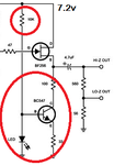
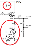
The RF amplifier design attached uses a simple bc547 and a LED (red circles) as a contant current source for the buffer amplifier FET (am I right?)

How should I measure the constant current at this point in order to replace this circuit with something like this one? **broken link removed**
 

Attachments

  • bias.png
    bias.png
    24.7 KB · Views: 134

Measure the voltage across the 33R resistor.
I = V/r

or simply replace the Led with a transistor.

The forward voltage drop of a led is approx ~1.2 V
Minus the transistor base emitter voltage 1.2 - 0.6 = 0.6.
So you will have approx 0.6 across the 33R.
Which is about right for the new transistor.
 
Last edited:
  • Like
Reactions: neazoi

    neazoi

    Points: 2
    Helpful Answer Positive Rating
Measure the voltage across the 33R resistor.
I = V/r

or simply replace the Led with a transistor.

The forward voltage drop of a led is approx ~1.2 V
Minus the transistor base emitter voltage 1.2 - 0.6 = 0.6.
So you will have approx 0.6 across the 33R.
Which is about right for the new transistor.

All right, just to make sure, so I just need to replace the LED with a BC547 like shown here?
According to wikipedia https://en.wikipedia.org/wiki/Current_source this is better than the simple led approach...
 

Attachments

  • bias.png
    bias.png
    29.7 KB · Views: 123

Yes, that looks about right.
 
  • Like
Reactions: neazoi

    neazoi

    Points: 2
    Helpful Answer Positive Rating
It depends what kind of LED you're using. A normal red LED has a voltage drop of about 1.7V. In that case the voltage across the 33 Ohm resistor is about 1V, and it should be replaced with 22 Ohms when changing to the transistor circuit.

I'd suggest measuring the voltage across the 33 Ohm resistor in the existing circuit to make sure.
 
  • Like
Reactions: neazoi

    neazoi

    Points: 2
    Helpful Answer Positive Rating
Well, the author of the original circuit does not specify the kind of LED to use. I have used a standard 5mm 3V diffused red led and I am able to see waveform at the output of the circuit as I should, but I do not know what he have used as a LED. Just to mention the LED does not seem to produce any light at all.

In either case, I should measure the volrage accross the 33R and then derive the current from the formula. Then I should place the lower transistor and measure the current again through the 33R. Then adjust the 33R untill I get the same current reading through it. How does it sound?
 

Sounds good. I don't think it will make much difference to the circuit, but it doesn't hurt to try.
 
  • Like
Reactions: neazoi

    neazoi

    Points: 2
    Helpful Answer Positive Rating
I think you will find out that the forward voltage drop across the base emitter junction of a small signal transistor at turn on, is closer to 0.6V than it is to 0.7V.

So your resistor value is r = 0.6 / I.
So if you want 20mA,
r = 0.6 / 0.02
r = 30.

I don't think +/- a couple of mA will make any big difference to the circuit operation.

Allright, so based on your calculations a 33R is just ok even with the lower replacement...
It is just a current bias of the RF amplifier, I think it won't make that much difference if it is not too accurate. It should basically enrure that the current does not change with volrage variations, but the reculator provides a stable voltage anyway.
 

It depends what kind of LED you're using. A normal red LED has a voltage drop of about 1.7V. In that case the voltage across the 33 Ohm resistor is about 1V, and it should be replaced with 22 Ohms when changing to the transistor circuit.

I'd suggest measuring the voltage across the 33 Ohm resistor in the existing circuit to make sure.

You were right about this. It needs to be around 20-22R. Yesterday I tried the several options discussed in this thread.
The LED circuit was actually using a 39R, the current was at 16.92mA and the voltage at the base of the transistor was 1.43v.
The modified transistor circuit, uses now a 22R, the current is 16.81mA but the voltage at the base of the transistor is now 1.14v.
Do you think this lower voltage causes any problem?
Nevertheless, the output waveform was the same in amplitude and any distortions on both cases.
 

My two cents.....

Most diffused RED LED's are GaAsP on GaP is 1.4V +/- 5%** + ESR*Id, which could be as high as 2V, but at low current such as the original cct. with < 0.5mA it will be at the minimum voltage. 1.43V measured is <3% of nominal tolerance.

The same for silicon transistors at low current it will be Vbe= 0.6V +/-5%** +ESR*Ic which can rise to 0.7 at moderate current and 1V at high base currents. Since Base current is Ic/hFE and collector current is low, base current will be minimal drop or 0.6V.

Verification
Thus the emitter current = 1.4-0.6=>0.8V/39Ω= 20mA ~ +/-15% incl R tolerance of 10% = 17~23mA. measured 16.93mA is at the low end of estimate.

** at room temp.

The modified transistor circuit will cutoff at two Vbe voltages for the main driver or 1.2V for low current and have a slope of ∂V+ / ∂Ic = Rb/hFE on the constant current of Ve/Re=Ic, which only becomes important ,if say the supply voltage increases. So it is pretty constant but increases by base current / beta.

Low Vbe is not a problem but supply regulation of constant current but it is not perfect as it is on the cusp of the Vbe curve but not much better than the LED for regulation.

To scale this design to higher current LED's such as 300mA with different transistors, a similar LED used on the base will be a more effective regulator as 1W LED's have an ESR of ~1Ω, and a 5mm LED@ 20mA has an ESR of 10~16Ω, which is much less than an zener or a transistor Vbe. So LED's make great Zener type regulators when driver past 10% or rated current. Here 0.5mA is a little shy of 10% rated current, so regulation could be improved but was adequate.

If you wanted to have tighter control of LED current, one would need to use a precision band gap reference such as in LM317 1.25V across ADJ and Output and put current limited resistor across those two terminals. THis is even simpler than the above circuits but all suffer from some effective voltage drop across the current sink/source of 2V min at minimum supply voltage.

Output stage


As this is a source follower is like an emitter follower, the source DC current must exceed the AC peak current in the output AC coupled load resistance of 500Ω at maximum swing to remain linear.

If you need to increase voltage swing, simply increase current sink value using parallel R's and keep in mind this method is inefficient but necessary for linearity, so Q may get hot and need attention for choice of device.

I hope this makes sense.
 

Status
Not open for further replies.

Part and Inventory Search

Welcome to EDABoard.com

Sponsor

Back
Top