Continue to Site

Welcome to EDAboard.com

Welcome to our site! EDAboard.com is an international Electronics Discussion Forum focused on EDA software, circuits, schematics, books, theory, papers, asic, pld, 8051, DSP, Network, RF, Analog Design, PCB, Service Manuals... and a whole lot more! To participate you need to register. Registration is free. Click here to register now.

UC3842A minimum Current and Voltage input

Status
Not open for further replies.

baby_1

Advanced Member level 1
Joined
Dec 3, 2010
Messages
415
Helped
1
Reputation
2
Reaction score
1
Trophy points
1,298
Activity points
4,277
UC3842A minimum Current and Voltage input(Help to reading Datasheet)?

Hello
i read more and more about UC3842A but i can't find the min voltage and current to bias UC3842A?could help me on this?
what does pin 2 do?
 
Last edited:
Have you read the datasheet?

The startup voltage for UC3842 is 15V minimum. After turnon the UC3842 can be run off any voltage greater than 9V.

The startup current is 0.5mA to 1mA. The operating current is between 11mA and 17mA.

All these are clearly mentioned in the datasheet. Go through the datasheet and a few application notes and you'll be clear regarding UC3842.

Hope this helps.
Tahmid.
 
  • Like
Reactions: baby_1

    baby_1

    Points: 2
    Helpful Answer Positive Rating
Hello
what does the pin 3 do in UC3842(Current sense)?
what does the pin 2 do in UC3842(VFB)?

---------- Post added at 18:02 ---------- Previous post was at 17:51 ----------

i downloaded lots of datasheet.but most of them they have a special internal Zener diode (36V,29V,..) and the maximum voltage is 30volt.i want to series a resistor between my source(325Dc volt) and pin7.what voltage should i assume on Pin7?
 

If you're going to use a resistor between 325VDC and pin 7, the internal zener will be used. If you see the Unitrode datasheet, you can see that it says that, when current is less than 30mA, the internal max voltage is self-limited. So, if you assume 30V, it's okay, I guess. What's more important is the startup current. 100k is a commonly used value for this resistor. If you assume 30V, the current will be 2.95mA. So, it's fine. But you must provide a solid auxiliary power supply to the UC3842, preferably from an auxiliary winding on the main transformer itself. This voltage should be about 20V. 2.95mA is enough to start the controller but not enough to keep it going and keep the converter working.

Do keep in mind the minimum input voltage and that the UC3842 must be started at the minimum input voltage. Also, connect a 100uF capacitor across VCC and ground.

---------- Post added at 19:49 ---------- Previous post was at 19:45 ----------

Pin 2 is used for output voltage feedback. Pin 3 is used for primary side current sensing.

You should go through this thread: https://www.diyaudio.com/forums/power-supplies/159951-65w-flyback-smps.html

You'll find loads of helpful information there.

Hope this helps.
Tahmid.
 
  • Like
Reactions: baby_1

    baby_1

    Points: 2
    Helpful Answer Positive Rating
Thanks
could you tell me why should i use an auxiliary power supply?if i put a 100microfarad capacitor to the line is it not enough?because if it want more current the capacitor could compensate it?(but not quick with high impedance 100Kohm resistor)

---------- Post added at 18:32 ---------- Previous post was at 18:29 ----------

if i remove this line(between my source 325dc volt and pin7)and use another power supply that use main transformer itself, whats the effect of this changes?it will be off all the time?
 

Let's assume that to drive the MOSFET, we need to provide a current of 100mA and for the UC3842 20mA. So, for example's sake, we need 120mA current. It'll take some time to charge the capacitor, but it's going to discharge very quickly. Each cycle, you need to drive the MOSFET, but the capacitor is probably not going to charge that quickly. So, the UC3842 might turn off, or even if it doesn't, the MOSFET may turn off. So, the output will be 0. So, the output will be 0 for some time, then you'll get output for a short time during which capacitor is charged, and then again 0.

And say, you had managed to make the capacitor charge quick enough. So, if we had an average current of 120mA, we would have a large loss. With 325VDC input and assuming the zener is rated at 30V, the loss in the dropping resistor would be 35.4W. Also, the condition for zener regulation is that the current should be less than 30mA, which as we can see, it clearly isn't. So, you risk burning the IC as well.

And so, you should use an auxiliary power supply.

Hope this helps.
Tahmid.
 
  • Like
Reactions: baby_1

    baby_1

    Points: 2
    Helpful Answer Positive Rating
Thanks My dear Tahmid
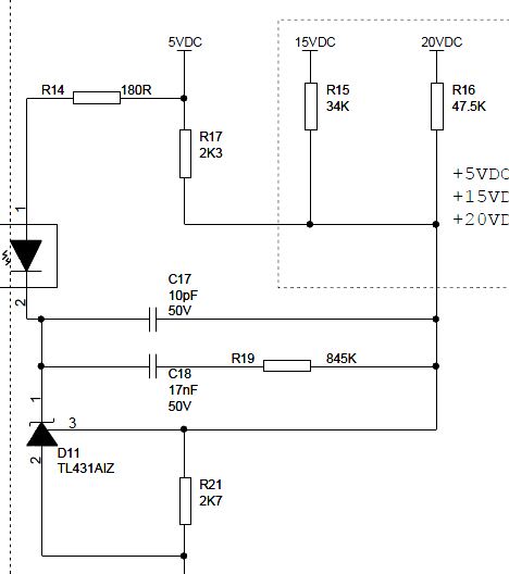
could you explain about the Tl431 and calculation?because i see a lots of circuit but i can't find the good calculation and realize how it work?

for example as you see this circuit.we have three output.i choose 20Volt and use the Tl431 calculatio formula
68_1338387230.jpg


gif.latex


so Vo=20(1+2.7/47.5)=21.13

it means if i have a 20 volt at my output Tl431 has told us that we have an error that should be correct.

what is my fault?
 

Hi
Vout = 2.5(1+R1/R2) . if you use two voltage divider resistors . ( top side is R1 and the other one R2 )
Best Wishes
Goldsmith
 

Status
Not open for further replies.

Part and Inventory Search

Welcome to EDABoard.com

Sponsor

Back
Top