Continue to Site

Welcome to EDAboard.com

Welcome to our site! EDAboard.com is an international Electronics Discussion Forum focused on EDA software, circuits, schematics, books, theory, papers, asic, pld, 8051, DSP, Network, RF, Analog Design, PCB, Service Manuals... and a whole lot more! To participate you need to register. Registration is free. Click here to register now.

Discrete potentiometer using resistor ladder- How to hold previous voltage?

Status
Not open for further replies.

faisal78

Member level 3
Joined
Aug 27, 2004
Messages
62
Helped
0
Reputation
0
Reaction score
0
Trophy points
1,286
Activity points
592
Hi
I would like to make a simple volume knob using discrete resistor ladder.
For example, using 15 discrete resistors, i can use a ADC to discretely define 16 voltage levels to determine the volume knob position.

The bad thing about this circuit is, as I have only a single "wiper", as I am going in between resistor "pad", there is a finite time that the ADC may sample 0V? this will happen every time i am going between resistor values.

How can I easily solve this electronically? I know I can solve it using daul "wipers" mechanically.
Even by using a Sample & Hold circuit, there may be an occurrence that I may sample 0V.

Any idea's?
 

I fear, the specification makes no sense.

Hi, I don't quite understand what you mean by this.
Basically the change of state between the resistors is not of fixed time.
It can be from 100ms up to 2 seconds.

For a 15 discrete level, operating at 2v, each step change will be 130mV each.
As you have said I can use a RC time constant of 2 seconds to slow the change for the 130mV.
But to get from 0V to 2v full swing with that RC constant, it may take up to 30sec which is too long.
 

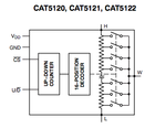
I would use a rotary encoder that outputs count up and count down pulses (like a mouse wheel) to drive a digital potentiometer.
The dial can be continuous and the pot. can have 16 taps or be continuously variable. Cost ~ a few bucks... in small volume.
Specsheet
Screen shot 2012-05-15 at 10.49.14 PM.PNG

Hope that is close to your fuzzy logic spec....
 

The bad thing about this circuit is, as I have only a single "wiper", as I am going in between resistor "pad", there is a finite time that the ADC may sample 0V?

Could you let 0V (or close to it) as an invalid entry to whatever reads the ADC sampling voltage?
This requires that all levels be shifted up by 130mV for example.

Kerim
 

I would like to make a simple volume knob using discrete resistor ladder....

The bad thing about this circuit is, as I have only a single "wiper", as I am going in between resistor "pad", there is a finite time that the ADC may sample 0V?
If you use a "make before break" rotary switch, the output is never 0V. When the switch is between two positions, the voltage will be between the voltages for those two positions.

It's the kind of switch used in normal "switched resistor" volume controls, where the audio signal goes through the switched resistor ladder. For finer control something like a 48 position switch is normally used.
 
As you have said I can use a RC time constant of 2 seconds to slow the change for the 130mV.
I didn't suggest a large time constant.

Depending on the ADC input current, a very small capacitor will be sufficient to hold the voltage. The respective time constant can be neglectible. You didn't consider the fact that the RC time constant changes in open circuit state

Ultimately you can add a high impedance buffer, which is still less effort than other possible solutions to detect an open circuit.

Of course the suggestions to use make-before-break switches or an incremental encoder are valuable as well. The latter is a standard solution in recent home appliances and home entertainement.
 

Hi,

Sorry, may I know what the use of the ADC is!
I mean is it hard reading 17 levels instead of 16 and ignoring the lowest one?

Sorry again if I misunderstood the main problem, but ADC means likely the presence of MCU.
Even in this case, if the MCU program cannot be altered then an external solution would be needed.

Kerim
 

Hello all,
thanks for your inputs.

The ADC is basically going to be measuring the voltage on the volume knob and adjust the audio gains accordingly.
However, we are also considering bypassing this altogether to save cost and just connect the volume knob directly to set the audio gains.
By doing this we avoid using a ADC and save some costs. But then we may have to use a "double wiper" type of knob which makes and breaks which prevents the 0v.
 

If you use a "make before break" rotary switch, the output is never 0V. When the switch is between two positions, the voltage will be between the voltages for those two positions.

It's the kind of switch used in normal "switched resistor" volume controls, where the audio signal goes through the switched resistor ladder. For finer control something like a 48 position switch is normally used.

I agree - this is probably the simplist & best solution. Make your wiper wide enough so that it touches 2 adjacent resistor pads while crossing over. You need to work out your resistor values though, depending on whether you use a ladder or just straight resistors.

Whether you now read this value via ADC and digitally control YET another device blah blah, or directly connect it to the analog output (like they did in the old days) will make no difference
 
Last edited:

Status
Not open for further replies.

Part and Inventory Search

Welcome to EDABoard.com

Sponsor

Back
Top