sdmuashr
Junior Member level 1
Hi,
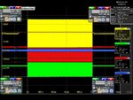
I have to measure drain and gate voltages of power transistors at around 120 MHz. The transistors' casing are soldered on PCB and the PCB has other circuitry also which is causing great trouble in measuring the drain and gate voltages at the time of transistors' functioning. As expected the gate and drain voltages appear in rectangular pulses which have both dc bias and rf component. However, the oscilloscope shows the magnitude of drain voltage pulse varying if the wires (which are soldered on one end at drain and gate of transistor and at the other end are connected to oscilloscope) are moved or contacted or if you make a hole with your hand (see picture below) and let that wire pass through that hole.
Please share your ideas or suggestions or experiences in this regard. Also, please provide material in as much detail as possible.
Last edited by a moderator:
