Continue to Site

Welcome to EDAboard.com

Welcome to our site! EDAboard.com is an international Electronics Discussion Forum focused on EDA software, circuits, schematics, books, theory, papers, asic, pld, 8051, DSP, Network, RF, Analog Design, PCB, Service Manuals... and a whole lot more! To participate you need to register. Registration is free. Click here to register now.

How to DIY a Portable Electric Carhorn

Status
Not open for further replies.

thegauntlet

Newbie level 4
Joined
Apr 28, 2012
Messages
7
Helped
0
Reputation
0
Reaction score
0
Trophy points
1,281
Location
Singapore
Activity points
1,350
I want to do up a portable carhorn for my bicycle. Since they're generally 12V, I'm thinking of using 3 or 4 3.7V 2500mAh 18650 Lithium Ion batteries connected in series so it'll go up to 11.1V or 14.8V. Is it as simple as connecting the horn with battery pack and switch? I'm thinking of using a very small push button switch that is rated, 0.5A and 240V. The horn I'll be using is rated 2.5A and 12V. I'd want it to be simple to save space and weight on my bicycle.

1. What can I do to be able to use this small switch and not get a bigger switch that has a higher current rating?
2. Do I need anything extra like a relay or fuse?
3. Also if I were to use a carhorn that draws a higher current, say 3-4A would it work with the 2500mAh batteries?

I'm not an electronics student nor have a background in electronics but I'd like to start learning it myself because you can do so much with electronics, be it building or repairing your own things.
 

A car horn will usually be designed to operate best at around 14V or a bit more - that's what the alternator gives the electrical system when the engine is running.

LiIon cells, although rated at 3.7V, actually give up to about 4.2V when freshly charged. That's why some LED flashlights will be instantly killed if they are only designed to run on non-rechargeable lithium cells (CR123) and someone puts in a rechargeable (RCR123) LiIon version of the cell. The voltage drops as the cell is depleted.

So, ideally you want about 14V. Four LiIon cells will give 14.8V to 16.8V, three will give from 11.1V to 12.6V.

I would try the three cells; you might find it quite loud enough. If not you could try four but that might damage the horn, especially if sounded for long periods. If the horn is a simple, mechanical buzzer type it will probably be OK with four, but if it is electronic then it might not. My guess is that you would get away with four because it's only a little over the top, but it's only a guess.

You do know that 18650 cells are quite hazardous? Search google for exploding LiIon packs (search for 'vents with flame', lol). That said, if your cells are normal retail ones, with a protection circuit on the end, and you keep them dry and don't abuse them or let them get too discharged, there should not be a problem. Don't use recycled laptop battery pack cells though, like I do, unless you fully understand the real dangers. Google will help in all this. If you already use them for your lighting, you probably know all of this though.

You can take safely take twice the capacity rating from a LiIon cell as current. So, 2500mAh will easily give you 5A. Some, especially IMR cells, can give much higher current (IMR are 10 times C I think). Check your cells.

Your switch will quickly die at high currents. The easiest way for you to switch it is probably to use a small relay. Relays are easily available with a 12V coil, that can switch 5A-10A or more. They are not that large; around a 2cm cube. You might even find a small one wherever you acquire the horn. The switch would connect the 12V to the relay coil, and the relay contact would connect the 12V to the horn.

Alternatively, you could use a power transistor instead of the relay, with a base resistor and a freewheeling diode to protect the transistor from the horn's back-EMF. Google will find you a circuit for 'transistor to switch a relay' - you will put the horn in place of the relay, but the search will get you circuits that have the diode. A 2n3055 transistor can handle 15A.
 
Last edited:
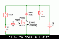
1+2) You can use a small switch to switch on a MOSFET or a relay, then that device can switch the high current to the horn. I've drawn two circuits below to show both ways to do it.

3) That should be OK, the battery will just discharge quicker.

 
Thanks for the circuit diagrams godfreyl! What software do you use to draw them? The MOSFET option would take up very little space yes? If I used the MOSFET option, I'll have to solder them on a perfboard? What are the differences between both and which would you recommend?

1+2) You can use a small switch to switch on a MOSFET or a relay, then that device can switch the high current to the horn. I've drawn two circuits below to show both ways to do it.

3) That should be OK, the battery will just discharge quicker.


Half of me prefers the MOSFET because it's a bit more efficient. The other half of me would go for whichever is cheapest. :)

The software I use is the free version of SIMetrix-SIMPLIS. It's simulation software. That means that after drawing the circuit, you can run a simulation to see what it does. You can check voltages and currents anywhere in the circuit, look at waveforms etc.

I cheated with this a bit, though, and used MSPaint to draw in the horn and relay.
 

I see, I think I'll be going with the MOSFET option because of the small size! What's the purpose of having a diode and the two resistors (1K resistors have different wattages, how do I select them?) THANKS! :D


Half of me prefers the MOSFET because it's a bit more efficient. The other half of me would go for whichever is cheapest. :)

The software I use is the free version of SIMetrix-SIMPLIS. It's simulation software. That means that after drawing the circuit, you can run a simulation to see what it does. You can check voltages and currents anywhere in the circuit, look at waveforms etc.

I cheated with this a bit, though, and used MSPaint to draw in the horn and relay.
 
Last edited:

Good questions!

The MOSFET is controlled by the voltage between the gate and the source. The gate has a very high resistance so almost no current flows into it.

When the switch is closed, it puts 12V on the gate to switch the MOSFET on (and a little current will flow through R2). When the switch is open, R2 pulls the gate down to 0V, to switch the MOSFET off.

R1 is more interesting. MOSFETs are fast and like to oscillate at high frequencies. Connecting R1 to the gate stops it from oscillating and turning into a radio transmitter. The resistor should be connected as close as possible to the gate, with nothing else connected to the gate. Don't even leave a long strip of copper on the perfboard connected to the gate.

The diode is there to stop the voltage on the drain from shooting up to a high value (which could damage the MOSFET), when the MOSFET switches off. The horn is an inductive load, so when the MOSFET switches off, the current through the horn does not stop instantly, but tries to pull the voltage up.

edit: R2 only dissipates about 0.15W, so a 1/4 Watt resistor would be OK, but a half Watt resistor would be safer. R1 doesn't dissipate any power, so it doesn't matter. I'd make them both the same because some places only sell resistors in packets of 10 anyway.

 
Last edited:

I see, so when the circuit is closed, the voltage will "trigger" the Gate to "close the circuit" between the Drain and the Source. I've bought all the parts, just waiting for them to arrive! I unknowingly bought a TAKAMISAWA 12V Relay not knowing it's a minature relay and can only switch up to 1A. I should have checked the current rating.

1. Anyhow regarding FoxyRick's answer. The 2n3055 works similarly too? Is the Base like the Gate and the Collector the Source and Emitter the Drain? But it's different because one's by Current and other Voltage? Sorry, I tend to ask questions all the time, I hope you won't mind :p The how do I know what Voltage is required to switch a certain MOSFET on? I read "https://www.edaboard.com/threads/54696/" but another opinion would always help!

2. I bought the Perfboard. How do I go about deciding how I'd place the components and soldering them? Your circuit diagrams are great but it's hard to visualize on the board itself.

3. I want a switch that's easy to press and mounted. I've seen these https://img.dxcdn.com/productimages/sku_12895_2.jpg on dealextreme and was thinking of getting them. Do stores sell these sort of switches or do I have to get them with the whole tailcap? Any idea what these are called? I suppose a switch just has have two pins/wires to connect to the power source so if I bought these I just have to cut the wire and solder it to my circuit yes?

4. What books/online resources are good to start learning electronics? There's so much to learn!


Good questions!

The MOSFET is controlled by the voltage between the gate and the source. The gate has a very high resistance so almost no current flows into it.

When the switch is closed, it puts 12V on the gate to switch the MOSFET on (and a little current will flow through R2). When the switch is open, R2 pulls the gate down to 0V, to switch the MOSFET off.

R1 is more interesting. MOSFETs are fast and like to oscillate at high frequencies. Connecting R1 to the gate stops it from oscillating and turning into a radio transmitter. The resistor should be connected as close as possible to the gate, with nothing else connected to the gate. Don't even leave a long strip of copper on the perfboard connected to the gate.

The diode is there to stop the voltage on the drain from shooting up to a high value (which could damage the MOSFET), when the MOSFET switches off. The horn is an inductive load, so when the MOSFET switches off, the current through the horn does not stop instantly, but tries to pull the voltage up.

edit: R2 only dissipates about 0.15W, so a 1/4 Watt resistor would be OK, but a half Watt resistor would be safer. R1 doesn't dissipate any power, so it doesn't matter. I'd make them both the same because some places only sell resistors in packets of 10 anyway.

 
Last edited:

Hi FoxyRick,

If I used a 12V relay would I still need a diode? Or is it only needed when I use a transistor to protect it? Thanks!

A car horn will usually be designed to operate best at around 14V or a bit more - that's what the alternator gives the electrical system when the engine is running.

LiIon cells, although rated at 3.7V, actually give up to about 4.2V when freshly charged. That's why some LED flashlights will be instantly killed if they are only designed to run on non-rechargeable lithium cells (CR123) and someone puts in a rechargeable (RCR123) LiIon version of the cell. The voltage drops as the cell is depleted.

So, ideally you want about 14V. Four LiIon cells will give 14.8V to 16.8V, three will give from 11.1V to 12.6V.

I would try the three cells; you might find it quite loud enough. If not you could try four but that might damage the horn, especially if sounded for long periods. If the horn is a simple, mechanical buzzer type it will probably be OK with four, but if it is electronic then it might not. My guess is that you would get away with four because it's only a little over the top, but it's only a guess.

You do know that 18650 cells are quite hazardous? Search google for exploding LiIon packs (search for 'vents with flame', lol). That said, if your cells are normal retail ones, with a protection circuit on the end, and you keep them dry and don't abuse them or let them get too discharged, there should not be a problem. Don't use recycled laptop battery pack cells though, like I do, unless you fully understand the real dangers. Google will help in all this. If you already use them for your lighting, you probably know all of this though.

You can take safely take twice the capacity rating from a LiIon cell as current. So, 2500mAh will easily give you 5A. Some, especially IMR cells, can give much higher current (IMR are 10 times C I think). Check your cells.

Your switch will quickly die at high currents. The easiest way for you to switch it is probably to use a small relay. Relays are easily available with a 12V coil, that can switch 5A-10A or more. They are not that large; around a 2cm cube. You might even find a small one wherever you acquire the horn. The switch would connect the 12V to the relay coil, and the relay contact would connect the 12V to the horn.

Alternatively, you could use a power transistor instead of the relay, with a base resistor and a freewheeling diode to protect the transistor from the horn's back-EMF. Google will find you a circuit for 'transistor to switch a relay' - you will put the horn in place of the relay, but the search will get you circuits that have the diode. A 2n3055 transistor can handle 15A.
 

The diode is there principally to protect the transistor, be it bipolar or MOSFET. When power is removed from the relay (or any) coil, the magnetic field around the coil collapses back into the coil, and the energy ends up causing a reverse voltage (called back EMF) across the coil connections. Because the relay is switched off, the voltage grows until it is large enough to break through whatever barrier is there - the transistor! The reverse-connected diode conducts this reverse voltage while it is small enough not to cause damage (to the diode, in this case).

That said, I would recommend the diode even if just a switch is used. Otherwise, the switch contacts will eventually suffer damage from arcing as the back EMF jumps the switch gap.
 
Hi, sorry I missed this earlier.
I see, so when the circuit is closed, the voltage will "trigger" the Gate to "close the circuit" between the Drain and the Source.
In this case yes, because you're just using it as an on/off switch. In other applications e.g. audio power amplifiers, MOSFETs are used in a more linear way, where the current from drain to source is controlled by the voltage between gate and source.

The how do I know what Voltage is required to switch a certain MOSFET on? I read "https://www.edaboard.com/threads/54696/" but another opinion would always help!
As explained in post two there but also:
  • Notice that the datasheet says VGS(th) = 2V min, 3V typical, 4V max. That means that if you buy a few of them, they're probably all a bit different to each other.
  • If you look at the graphs on the datasheet, you'll notice that Vgs for a given current changes with temperature as well. Neither of those points matter here, but do make life difficult when you're designing something like an amplifier.
  • If you increase the gate voltage too much, you damage the MOSFET. Vgs(max) is typically about +-12V. Zener diodes are often used to limit Vgs to protect the MOSFET. I didn't bother with a Zener in this circuit because your battery voltage is only about 12V to 14V and the IRF530 datasheet I looked at says Vgs(max) = 20V, so it should be OK.
The datasheet linked to in that thread is a bit fuzzy and it's hard to see what's going on in the graphs. This one from Fairchild is much easier to read: http://www.datasheetcatalog.org/datasheet/fairchild/IRF530.pdf

A few tips about datasheets: If you Google a part number (e.g. IRF530), you'll normally find links to a number of datasheets. It's worth looking at a couple of different ones as some give more information than others. Often you'll get links to sites like datasheetcatalog.com. Those are great, e.g. here's the link I first followed from Google: http://www.datasheetcatalog.com/datasheets_pdf/I/R/F/5/IRF530.shtml. Tip - the ones with really big file sizes don't contain lots more information; the file size is just bloated because they're bad scans of old paper documents.

The 2n3055 works similarly too? Is the Base like the Gate and the Collector the Source and Emitter the Drain? But it's different because one's by Current and other Voltage?
Almost. Base = Gate, Collector = Drain, and Emitter = Source.
With a BJT (e.g. 2N3055 or BC547), you have to raise the base-emitter voltage to about 0.7V to switch it on. Current then flows into the base, and collector current = base current * current gain. The base-emitter voltage only rises slightly as current is increased. For BJTs, current gain is the important (and badly defined) parameter. e.g. IIRC, A 2N3055 has current gain = 20 Min, 50 typical, 70 max. And of course it varies with temperature, collector current etc. :roll: If you wanted to replace the IRF530 with a 2N3055 in this circuit, R1 would have to be 100 Ohms or lower to get enough current into the base. You'd need to use a fairly big power resistor and it would get hot.

I bought the Perfboard. How do I go about deciding how I'd place the components and soldering them? Your circuit diagrams are great but it's hard to visualize on the board itself.
***Most important: The metal tab on the MOSFET is connected to the drain, so don't let it touch any other metal connected to the circuit or the battery. The MOSFET probably won't need a heatsink, but if you do want to bolt it to a heatsink or other metal, then use a mica insulating washer and some thermal paste. As a rule of thumb - if you can hold your finger on it, it's not too hot.

Most transistors, ICs etc have 2.5mm pin spacing, which makes them easy to fit on perfboard. I have a nasty feeling the IRF530 has 3.5mm pin spacing. If that's the case, you can probably fit it on diagonally, it will just look weird. If you're going to mount it elsewhere and connect it to the perfboard with wires, keep the wires as short as possible. It would probably be best to solder R1 directly to the MOSFET, and connect the other end of it to the perfboard.

The resistors and diode can either be mounted flat on the board spanning 3 or 4 holes, or mounted vertically with the wire bent over to go into an adjacent hole.

If the battery is going to be more than a couple of inches from the rest of the circuit, then it's a good idea to put a power supply decoupling capacitor (e.g. 100uF electrolytic) on the circuit board, connected between the positive and negative supply rails.

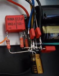
Having said all that, the circuits so simple I don't think I'd use a perfboard at all, but just use point to point wiring. i.e. Bolt the MOSFET onto something and solder the other components directly to it. See the pic below for an example of that technique. (There's a power amp chip bolted to the aluminum behind the large red capacitor). There's another example here: http://dogbreath.de/Chipamps/ThreeResAmp/ThreeResAmp.html. I don't think I'd want to cut the component leads as short as he did, though!

I want a switch that's easy to press and mounted. I've seen these http://img.dxcdn.com/productimages/sku_12895_2.jpg on dealextreme and was thinking of getting them. Do stores sell these sort of switches or do I have to get them with the whole tailcap? Any idea what these are called?
I don't know. If you have a look at an online store like digikey, mouser or rs-online, you should be able to get an idea of what's available and what they're called.

What books/online resources are good to start learning electronics? There's so much to learn!
There's a thread on this forum somewhere about that. I followed some of the links a couple of days ago, and this one looks fairly good (if incomplete): http://www.allaboutcircuits.com/.

One of the others was a website with more advertising than useful content, and another was a 6MB PDF download that was mostly about digital electronics and didn't cover the basics at all.

"The art of electronics" by Horowitz and Hill is a really good paper book.

 
Thanks FoxyRick! So if there's some sort of coil (be it relay or horn) that would cause a back EMF a diode should be placed in parallel with it to protect the circuit? If I used a relay to power the horn would I then use 2 diodes? One for each "coil"?

Do some relays have an internal supressing diode?

The diode is there principally to protect the transistor, be it bipolar or MOSFET. When power is removed from the relay (or any) coil, the magnetic field around the coil collapses back into the coil, and the energy ends up causing a reverse voltage (called back EMF) across the coil connections. Because the relay is switched off, the voltage grows until it is large enough to break through whatever barrier is there - the transistor! The reverse-connected diode conducts this reverse voltage while it is small enough not to cause damage (to the diode, in this case).

That said, I would recommend the diode even if just a switch is used. Otherwise, the switch contacts will eventually suffer damage from arcing as the back EMF jumps the switch gap.
 
Last edited:

I've never used a relay with an internal diode, but apparently they do exist.

As to the question: do you need another diode to protect the relay's switch contacts from the horn's back EMF? - Good question!

If you were switching another strongly inductive load (big coil, transformer, etc.) from the relay, then quite possibly a protection diode for that would be needed. See here: **broken link removed**

However, your relay should have much more robust contacts than a push-button switch and should handle the arcing. Plus, assuming that the horn is the mechanical type (which is actually a bit like a relay but with its coil power wired through the normally-on relay contact) then I would guess that any arcing would likely go through its own contacts. These are designed for it, so that's fine.

I don't think it is usual to include a second diode in this case, but it certainly won't harm anything. Probably no need for one though.

Here's an introduction to automotive relays, in case it is of help:

http://www.autoshop101.com/forms/hweb2.pdf
 

FoxyRick

Take godfreyl's circuit on the right as an example (http://obrazki.elektroda.pl/96_1335617202.gif)

If I used a horn switch, relay, horn and power source.
Could I do without a diode because my switch will be dealing with low currents and relay/horn circuit is independent of the switch?
OR is there a possibility the back EMF from the horn can reach the horn switch?
I understand the need of a diode when a transistor/mosfet is used but what about when a relay is used?
Can the relay's back EMF reach the horn switch's contacts?

I'm also confused over mechanical and electronic horns. Doesn't mechanical horns also use electricity to induce a magnetic field to vibrate a diaphragm of sorts?

As for the 18650 batteries. The ones I bought are protected. If I keep them dry and don't leave them charging unattented they should be fine? What do you mean letting them get too discharged?


I've never used a relay with an internal diode, but apparently they do exist.

As to the question: do you need another diode to protect the relay's switch contacts from the horn's back EMF? - Good question!

If you were switching another strongly inductive load (big coil, transformer, etc.) from the relay, then quite possibly a protection diode for that would be needed. See here: **broken link removed**

However, your relay should have much more robust contacts than a push-button switch and should handle the arcing. Plus, assuming that the horn is the mechanical type (which is actually a bit like a relay but with its coil power wired through the normally-on relay contact) then I would guess that any arcing would likely go through its own contacts. These are designed for it, so that's fine.

I don't think it is usual to include a second diode in this case, but it certainly won't harm anything. Probably no need for one though.

Here's an introduction to automotive relays, in case it is of help:

http://www.autoshop101.com/forms/hweb2.pdf
 

OK... first, the difference between a mechanical horn or buzzer, and an electronic one:

An electronic one will use a loudspeaker or piezo sounder, with a built-in sound-producing circuit and amplifier to drive the speaker. They cause no issues with back EMF. Generally, a car horn is the cheaper mechanical variety though...

A mechanical one uses a similar method to a relay, or an old-style electric doorbell or alarm bell, to create the sound. They have a coil electromagnet, that when energized moves an armature (like the clapper in an electric bell) or diaphragm (like the cone of a speaker). It is the movement of the armature or diaphragm that creates the sound waves.

This moving part is connected to an internal switch contact, like the contacts inside a relay. The wiring inside is arranged so that the power to the relay goes through the contacts, which are normally touching and so are like a switch that is turned on. When the armature moves far enough however, the contact opens, breaking the circuit and cutting the power to the coil. So, the armature moves back (it is made springy), again like the contacts on a relay. When it moves back far enough, the contact touch again, turning the coil back on, and the cycle repeats.

This causes the moving part to vibrate continually backwards and forwards, producing the sound.

Such mechanical sounders can create an issue with back EMF themselves (nothing to do with the relay in the circuits) because of the coil. Remember, switching off the power to any coil causes this back EMF. If you hold a radio, tuned to an AM station, near a mechanical buzzer you will most likely hear loud crackling when the buzzer sounds due to the back EMF causing interference.

...

So, both the horn itself, and the relay, contain coils that can cause back EMF.

Back EMF can reach hundreds to thousands of volts if not allowed a way to flow away easily when the coil is turned off. The revered diode gives the back EMF that easy path.

The result is that both the relay and the horn can produce back EMF that could damage whatever is switching that part on (or rather, off). The relay will damage its transistor or push button switch contacts, and the horn will damage the relay contacts (or whatever else switches the horn).

...

In godfreyl's circuit, the one on the left, you will see the protection diode across the horn, so the assumption there is that the horn does need one. Given that it is being turned on directly by a transistor, it certainly is needed, just as it would be if you put a relay in that circuit in place of the horn. The back EMF produced would instazap the transistor.

The switch in that circuit does not have a diode because it is only directly switching on the transistor, so no back EMF reaches the switch.

In the right-hand circuit, there is also a diode across the horn, but now we have a second back-EMF producing part, the relay. The diode is protecting the relay's contacts from the horn's back-EMF. I would say that another diode is needed across the relay coil, to protect the push-button switch's contacts. Although the switch is nowhere near as sensitive to the back EMF as the transistor, the back-EMF will go high enough to cause an arc across the switch every time is is released. This will burn and could eventually cause the switch to fail.

...

The 18650 cells should be fine if they are protected. The protection circuit will cut power if the charge falls too low. That's one of the things they are for. In unprotected cells, if the charge level drops too far, they are dangerous to recharge because crystals of metallic lithium start to grow inside the cell. Once this starts, the cell can spontaneously short internally through the crystals and burst into flames.
 

Status
Not open for further replies.

Part and Inventory Search

Welcome to EDABoard.com

Sponsor

Back
Top