Continue to Site

Welcome to EDAboard.com

Welcome to our site! EDAboard.com is an international Electronics Discussion Forum focused on EDA software, circuits, schematics, books, theory, papers, asic, pld, 8051, DSP, Network, RF, Analog Design, PCB, Service Manuals... and a whole lot more! To participate you need to register. Registration is free. Click here to register now.

hbridge drive inverter (question)

Status
Not open for further replies.

babatundeawe

Full Member level 5
Joined
Apr 12, 2007
Messages
244
Helped
16
Reputation
32
Reaction score
12
Trophy points
1,298
Location
Nigeria
Activity points
2,738
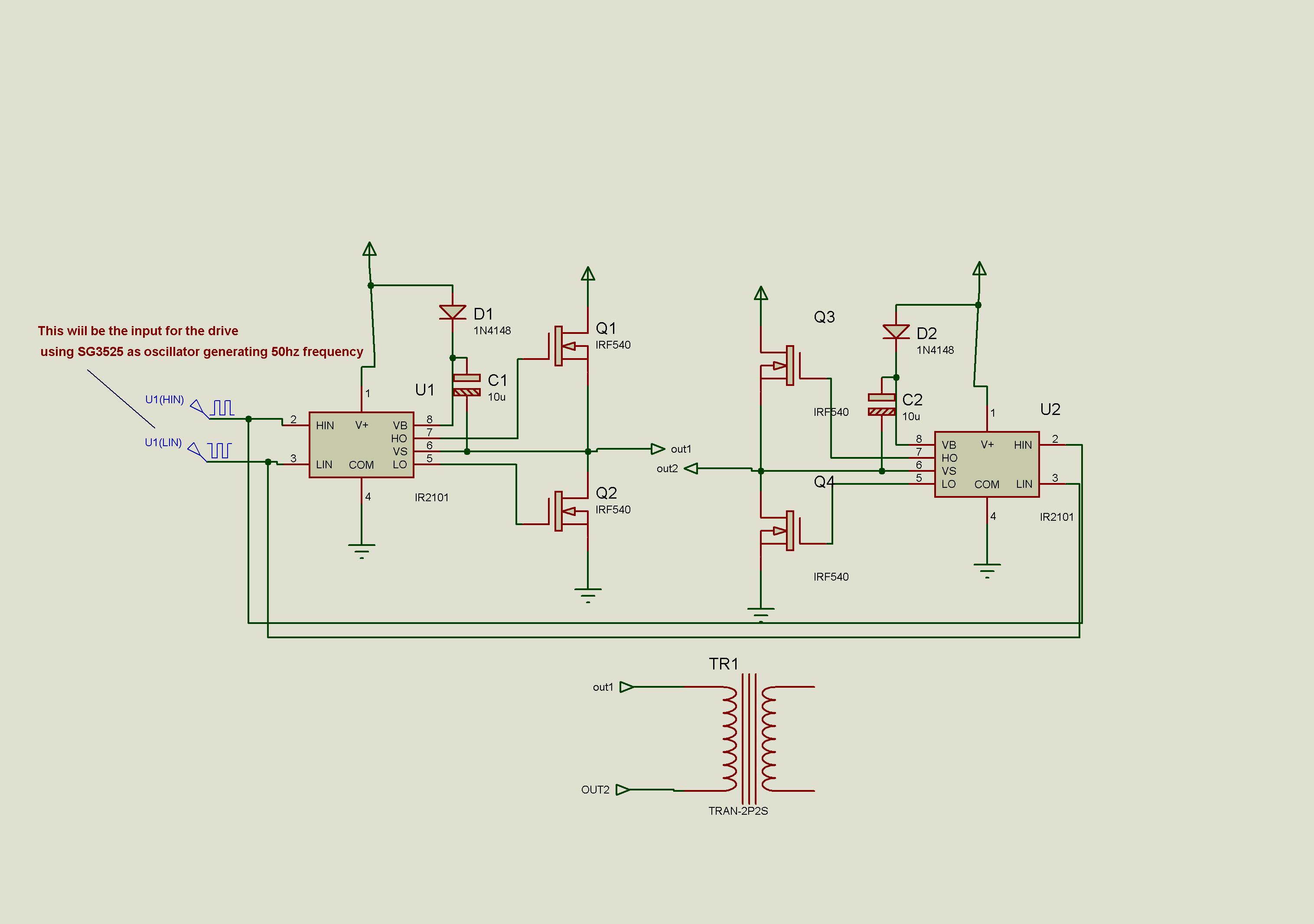
hi guys, please i am preapring to build an inverter for home use and i wish i can use the hbridge drive but i ve got some confusion.

1. can i use it to drive a center tapped transformer
2. will it work properly at low frequency of 50hz?

i intend using ir2110 halfbridge in full bridge mode.

thanks for your help.
 

Hello,

I don't see problems when running from 12V or 24V supply. You have to dive into the bootstrap power supply (capacitor with diode that supplies the high side driver), to make sure you have sufficient stored charge in the bootstrap capacitor to make 10ms pulses.

You need two of these chips to make a full bridge. When using 12V supply, you will get an output swing (between the floating outputs) of +/-12V. You can use a transformer that outputs 12V when supplied with your local mains voltage.

You don't need a center tap. The center tap you use for a push pull topology. Not to forget, you need 4 capable mosfets.
 

    V

    Points: 2
    Helpful Answer Positive Rating
thanks wim for prompt response. it is ok to use a 220v to 12v transformer as u ve said. please here is another. i m planning to use sg3525 or tl494 ( i gues i will stick with 3525) using the pwm technique. do i need to worry about the dead time or the 500ns is sufficient for the 50hz frequency. i intend using the low side drive as it is easy to config wit nmosfet. thanks
 

Hello,

Can you make a drawing (sketch) of what you want to do (inclusive switching frequency)? This may avoid confusion.
 

Hello babatunde ,you have to decide which topology to use so that members will understand what you want to do,you can used either push pull or H-bridge but remember if you are using H-bridge you will need IR2110 or any suitable h-bridge driver ic and more mosfets .
 

here is the sketch of what i intend to do. please me know if i m right
 
hello Babatunde,

This is a full bridge (H-bridge) topology. This avoids the leakage inductance problems that you may have with a push pull topology, and you don't need a center tap. you need some dead time to avoid cross conduction between high side and low side mosfets. In case of modified sine wave, you need a dead time in the ms range.

You mentioned PWM. Would you like to make a sinewave by using a higher switching frequency or just a modified sinewave directly at 50 Hz?

I would add some gate resistance in all mosfets to get smooth switching (avoids transients, ringing and EMI problems).
 
thanks wim. yes for now i am planning to make a moodified sinewave 50hz inverter, as i m still brushing up my knowledge of generating sine wave with pic but now its d modified version dat i need. and again
1.how can i calculate d dead time for the circuit.
2.so i guess d sketch is ok if i connect it as drawn and including the resistance.
3.i am planniing to use a toroid made from wound laminated steel. hope its ok too
4. how many transistor will i use aside from the four say for 500 to 1000w.
i m uploading the picture of torroid can u guess the rating. thanks..

here is d dimension of the torroidd as measured.

od = 16cm
id = 8cm
height = 8cm
thickness = 4cm


It looks like a bare core, are you going to wind your own transformer?

If so find a good reference on transformer design that discusses safety issues as you don't want an inverter with dead family members. You may also consider to use more turns to reduce the flux in the core. This will reduce the power rating of the transformer, but increases the efficiency under low and moderate loads.

I have a 625VA toroidal transformer sitting overhere that has OD=0.16m (with wire, so the actual core is smaller). So if it is a good quality core, >500VA should be possible.

About your 1000W. From 12V supply that is 84A average consumption from your battery. As you may know you need to have a good reserve, so you bridge should be able to switch more then that (think of 150A).

Number of mosfets.
Imagine you use 6 mosfets (IRF 540) in parallel, each with its own gate resistor.
Each mosfet has 0.12 Ohm Rdson (100 degrees die temperature). The resistance for each of the four switches will be 19 mOhm. Each switch uses 6 mosfets.
At 84A 50% duty cycle that will be 70W dissipation/switch. As you have 4 switches, dissipation will be 280W. In real world it will be more as you use modified sinewave.

So simple calculation shows what to expect. As you are using a full bridge, you may select mosfets with a lower voltage rating (as you don't get voltage spikes due to leakage induction of the transformer). Such mosfets have less Rdson, hence less dissipation and better efficiency.

Dead time.
As you want to use modified sine wave, dead time (that is the time duration that all mosfets are in the off state) will be about 7 ms.

Probably you will not invest in large electrolytic capacitors. In that case this concept will work well when you place all electronics close to the battery. Otherwise will get large voltage spikes at the supply of the bridge.
 
It looks like a bare core, are you going to wind your own transformer?

yeah i will wind it myself thats no problem

You may also consider to use more turns to reduce the flux in the core. This will reduce the power rating of the transformer, but increases the efficiency under low and moderate loads.

please can you explain a little about this.

I have a 625VA toroidal transformer sitting overhere that has OD=0.16m (with wire, so the actual core is smaller). So if it is a good quality core, >500VA should be possible.

i pray i can push it up to 1KVA

About your 1000W. From 12V supply that is 84A average consumption from your battery. As you may know you need to have a good reserve, so you bridge should be able to switch more then that (think of 150A).

ok here i planned to use 24volts, so if i could go by your calculation. it should be 42A on average consumption and that should be around 75-80A from the bridge

Number of mosfets.
Imagine you use 6 mosfets (IRF 540) in parallel, each with its own gate resistor.
Each mosfet has 0.12 Ohm Rdson (100 degrees die temperature). The resistance for each of the four switches will be 19 mOhm. Each switch uses 6 mosfets.
At 84A 50% duty cycle that will be 70W dissipation/switch. As you have 4 switches, dissipation will be 280W. In real world it will be more as you use modified sinewave.

please here i need to understand this part. do u mean for the full bridge i will need 24 mosfets that is six mosfets in parallel on the high side and six mosfets in parallel down for each of the half bridge. please explain

So simple calculation shows what to expect. As you are using a full bridge, you may select mosfets with a lower voltage rating (as you don't get voltage spikes due to leakage induction of the transformer). Such mosfets have less Rdson, hence less dissipation and better efficiency.

Dead time.
As you want to use modified sine wave, dead time (that is the time duration that all mosfets are in the off state) will be about 7 ms.

how can i achieve this with SG3525

Probably you will not invest in large electrolytic capacitors. In that case this concept will work well when you place all electronics close to the battery. Otherwise will get large voltage spikes at the supply of the bridge.

thanks i am very grateful for your time
 

Number of switches,
correct, I used 6 per switch in the example calculation, so you need 24 mosfets, and still from 12V supply the loss is very high (at full load).
Using 24V is a good idea as it halves the current, hence conduction loss of the mosfets drops to 25%.

Transformer loss.
If you design your transformer for maximum efficiency at full load, you will use large flux density in the core (to reduce copper loss, but higher core loss).

The core loss (that is heat generated in the band steel core) remains the same, even under no load. So with moderate to low load, the inverter still draws significant power from the batteries.

By accepting lower flux density in the core (that means more prim. and sec. turns), you reduce the core loss, but you get more copper loss. However at moderate load the copper loss reduces significantly (as P = I^2*R).

Regarding the dead time:
If you can't make it with the SG3525, you may use a separate oscillator that provides the correct pulses for the driver chip.
 

please, which of the losses is greater. copper loss or core loss?
 

When the transformer isn't loaded, you only have the primary magnetizing current, so core loss is dominant in that case. At high current the copper los will be dominant and the core loss remains the same as under no load condition.

The flux in the core is dominated by the primary voltage, and that doesn't change (it may even become a bit less due to copper loss).
 

hi wim.

thanks for your help all the way i did try the inverter out with the said design. and it worked. though i didnt try it out on the core i posted just used a small transformer lying around and i was glad i did.

now i think i am going to go for a pwm sinewave inverter as you have sugested, cos i ve been taking my time to study how generate sinewaves wit pic.

thanks for your assistance.
 

Status
Not open for further replies.

Similar threads

Part and Inventory Search

Welcome to EDABoard.com

Sponsor

Back
Top