Continue to Site

Welcome to EDAboard.com

Welcome to our site! EDAboard.com is an international Electronics Discussion Forum focused on EDA software, circuits, schematics, books, theory, papers, asic, pld, 8051, DSP, Network, RF, Analog Design, PCB, Service Manuals... and a whole lot more! To participate you need to register. Registration is free. Click here to register now.

[SOLVED] Logic circuit for power on and off

Status
Not open for further replies.

faisal78

Member level 3
Joined
Aug 27, 2004
Messages
62
Helped
0
Reputation
0
Reaction score
0
Trophy points
1,286
Activity points
592
Hello
Need some advise.
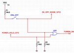
I am designing a simple power supply enable circuit. Please see attached schematic.

The On OFF switch would be logically "OR"ed together with a MCU GPIO.

The initial state of the POWER_HOLD_GPO would be LOW.
Once the ON switch is pushed, it will ENABLE the power regulator and also the MCU.
From then, the POWER_HOLD_GPO would be configured as output HIGH.

To turn off, when the switch is opened, it will drive the line LOW and the ON_OFF_SENSE GPIO (input) to the MCU will sense it and start the power down sequence and save criticial info. Once its done it will set POWER_HOLD_GPO low and it should shut off the power regulator.

My problem is, if during the power off sequence (ON_OFF_SWITCH =L & POWER_HOLD_GPO =H) and the MCU is within the power down sequence, and the ON/OFF switch is suddenly closed quickly enough prior the POWER_HOLD_GPO going LOW, the POWER_REGULATOR would be remain enabled, however the MCU has thought it would been powered down.

How do I avoid this state?

Any thoughts
 

Attachments

  • on_circuit.jpg
    on_circuit.jpg
    135.9 KB · Views: 117

By software: Use ON_OFF_SENSE_GPIO as an interrupt input which is still enabled during the MCU power down routine.
 

By software: Use ON_OFF_SENSE_GPIO as an interrupt input which is still enabled during the MCU power down routine.

Hi erikl
Yes, the backup plan to for my MCU to poll/interrupted by the ON_OFF_SENSE GPIO to stop the power down process.
The only thing is, there still might be a small (but unlikely) window of opportunity for the state to occur.

I am hoping that there is a logical fail safe way of preventing this from a logical point of view, maybe by using flip flops of more elaborate array of gates.

I'm pretty sure this application is seen in many electronics products, and I wonder how they had overcome it.
 

I am hoping that there is a logical fail safe way of preventing this from a logical point of view, maybe by using flip flops of more elaborate array of gates.

Hi faisal,

of course there's always a hardware solution possible, it depends however, how you want to react to such event: closing the ONb_OFF switch literally (in your case) means starting up the MCU and then enabling the power regulator. Is that what you intend to arrange for, also by this intermediate event? Or would you consider it as an operator error and neglect it, going on with the MCU power down sequence, and disable the power regulator anyway? These 2 different reactions would require different hardware circuits.

By using the a.m. software solution you can react as you like, of course. Even easily change it later on, if you want a different reaction.

BTW: manually activated switches always should get debounced -- by hard- or software -- otherwise there's a chance of malfunction. Debouncing such a switch -- independent of this being done by hard- or software -- always costs several milliseconds, so a hardware solution wouldn't be any faster than a software one.

Hello erikl,
Thanks for your replies.
I just realized that my schematic wasn't embedded in the first post, so I am attaching it so you can understand my current implementation.

The software solution on polling the state of ON_OFF_SENSE_GPIO is the current plan. Should the ON_OFF switch be closed during the power down software routine, it would be interrupted and remain to be turned ON. But as you can see from the logical state, the output of U2A OR gate would always remain logical HIGH (turning ON the regulator, or preventing it from turning OFF) if the ON_OFF switch remain closed.

Should I be concerned on the power up (when regulators are ramping up to the steady state voltage?) on the logical output?
 

Attachments

  • on_circuit.jpg
    on_circuit.jpg
    135.9 KB · Views: 104

I just realized that my schematic wasn't embedded in the first post, so I am attaching it so you can understand my current implementation.
It was already available -- otherwise it wouldn't have been possible to give you a detailed answer.

The software solution on polling the state of ON_OFF_SENSE_GPIO is the current plan. Should the ON_OFF switch be closed during the power down software routine, it would be interrupted and remain to be turned ON. But as you can see from the logical state, the output of U2A OR gate would always remain logical HIGH (turning ON the regulator, or preventing it from turning OFF) if the ON_OFF switch remain closed.
You didn't tell how you would like to react, s. my former answer.

Should I be concerned on the power up (when regulators are ramping up to the steady state voltage?) on the logical output?
Depends on which equipment the regulator is supplying power to. If it supplies VDD=5V and/or the MCU, you should of course be concerned. From which power supply does the ONb_OFF switch get its VDD=5V (and delivers 2.5V to the ON_OFF_SENSE_GPIO signal and to the upper input of U2A)? And the U2A gate supply? Are they supplied by the same power supply which should be started by the POWER_ON signal? Impossible without an accu/battery backUp!
 

It was already available -- otherwise it wouldn't have been possible to give you a detailed answer.


You didn't tell how you would like to react, s. my former answer.


Depends on which equipment the regulator is supplying power to. If it supplies VDD=5V and/or the MCU, you should of course be concerned. From which power supply does the ONb_OFF switch get its VDD=5V (and delivers 2.5V to the ON_OFF_SENSE_GPIO signal and to the upper input of U2A)? And the U2A gate supply? Are they supplied by the same power supply which should be started by the POWER_ON signal? Impossible without an accu/battery backUp!

Sorry, I may have left out critical details on the supplies. See below.
The plan is for the VDD=5V powering the logic (U2A) shall be powered via batteries always.
The Power_On signal is going to be used to a bunch of power regulators (also sourced from battery) to power the MCU/Audio circuits.

Power_ON = output from U2A logic powered via VDD=5v (always turned On)
Power_hold_GPO & ON_OFF_SENSE_GPIO will be powered from a separate regulator which enable line is via Power_ON.

So your current logic should work well -- if the 2.5V (voltage divider R2/(R2+R3)) supplied via the ONb_OFF switch are sufficient both for the ON_OFF_SENSE_GPIO signal and the upper input to U2A.
 

Status
Not open for further replies.

Similar threads

Part and Inventory Search

Welcome to EDABoard.com

Sponsor

Back
Top