Continue to Site

Welcome to EDAboard.com

Welcome to our site! EDAboard.com is an international Electronics Discussion Forum focused on EDA software, circuits, schematics, books, theory, papers, asic, pld, 8051, DSP, Network, RF, Analog Design, PCB, Service Manuals... and a whole lot more! To participate you need to register. Registration is free. Click here to register now.

Lecroy 9310M Oscilliscope help

Status
Not open for further replies.
14.7 volts at that point. :smile: I must have moved ground.

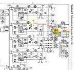
Check power supply voltage to Video board.

G4 122.5
G2 655.
G1 68.2

15
60.
 
Last edited:

Let’s recap:
For Q1 need to measure
Collector :14.7 V
Base : 3V
Emitter: 2.3V
Otherwise Q1 defective…
:cool:
 

Q1 on video board Collector 5.V Emitter 01V, Base 1 volt. On board it's q301. replaced with NTE 107 still same.
 

Attachments

  • Power supply L.JPG
    Power supply L.JPG
    164.1 KB · Views: 80
Only voltage I found was at J5 -15 / +15 and 5 volts. F1 glass fuse is Ok. My Ham buddies are saying trash it
 

Still it's not clear why missing the 15V power supply on the crt board.
Follow the PCB traces and wires to the connector up to the main power supply board, and look for joints where the solder looks black or corroded, or look for cracks in the solder joints, cracks in the PCB, and so on…
 
Need to check the fuse on the 15V power supply.

Ok I just checked the output voltage from T1 on the power supply. Input voltage is 158 - 160 volts all legs. the output is 0 voltage on all output legs now. did have -15 com +15, +5 volts on J5 but missing now. I am hearing a ticking also from the supply seem to becoming from T1. all voltage from the Ac to T1 is running about 158-160 volts. What do you think. T1 fried ?.

Bruce/ TZY
 

Ticking coming from a SMPS usually indicates the power supply is failing to start up, problems with the load, bad electrolytic capacitors, the regulation loop is broken somewhere... In this situation the power supply it is in a repeating cycle of starting up, being unable to limit the regulated voltages to normal values, and shutting down, over and over again.
Check for short circuits disconnecting J1- J5 one by one, also check for lose wires/bad joints in the power supply…
 
Ok. I checked all. I pull the T1 transformer out and hard wired the prime . There is no output voltage from the secord on all pins. I would say the Transformer is burned. I only have these numbers. PTOO4, T60014-01,

---------- Post added at 11:43 ---------- Previous post was at 11:23 ----------


Problems related to the SMPS transformer are very rare. This is not a very common fault, though if the rest of the circuit appears in a good working order, the transformer has to be checked.
The SMPS transformer is producing AC voltage, and this switching action is very fast, typically switches at speeds around 20-50 kHz. If you would like to test the output of the SMPS then place your multimeter probe after the secondary diodes output pin and check the DC voltage.

Based on the initial symptoms I have concluded that the main power transistor (Q3) is working and I suspect the possibility of shorted internal diode in secondary winding, loose wiring, cold solder joints, broken connections and burnt insulation or something shorted after the secondary output diodes, can all cause problems.

Set your meter to ohm range and check all the secondary output (after diodes) between of ground and all the output voltage line. Try to put the red probe to the cold ground and the black probe to each of the outputs of secondary lines. It should measured only high values readings, due to the main board resistance. Checking the negative outputs impose to reverse the meter’s probe.

If any output voltage lines showed low ohms readout, then suspect that there is problem in that output circuit. First try to check the rectifier diodes for that circuit. The diode should check almost a dead short in one direction, and an open for reverse. After troubleshooting the SMPS secondary section for some time and if rectifier diodes pass tests, try to remove connectors one by one at a time to isolate the short circuit. Several faults are possible in the horizontal/vertical deflection area like:
output transistor Q201 (check the resistance) , D202 diode (check for leakage) or even some (ceramic) capacitors shorted.
 
On reply # 24. I may have missed the fuse. I checked the main fuse F1 at the B+ line voltage. Can you tell me what these Fuses look like. I can't locate these on the board. I place the transformer back on the board. I placed the Multimeter on AC and took voltage reading at the pins. ( the power supply is removed and not connected to any drain) All pins were 122 volts. On DC no voltage!. I plan on working and doing the above testing this weekend. Thanks again for all you help.

Bruce / TZY
 

Hello!

I spend a ridiculous amount of time fixing the PSU of a dead 9314 - it was really wierd how it managed not to work. In the end I replaced one of the opto-couplers that initially measured OK and got the PSU working. I could check which one it was if you are interested. One thing I did was to attach a variable transformer. Weirdly it worked in some voltage ranges and not others. Once I got it partially working I could measure my way to the problem. Not easy though so don't feel bad if it takes a while, you will get there - very educational on SMPS though. But be careful though as high voltages can sting a bit.

I got stuck once I got the scope running with a strange error message and have been trying to get someone to read the EPROMS to files to check that mine are OK. Do you have a EPROM reader and could read them from your unit? It's a good idea anyway. I have had EPROMs on other instruments go bad from old age (those UV erasable units are not meant for eternity!) and then it's nice to have a back-up.

Best regards
 

Status
Not open for further replies.

Similar threads

Part and Inventory Search

Welcome to EDABoard.com

Sponsor

Back
Top