Continue to Site

Welcome to EDAboard.com

Welcome to our site! EDAboard.com is an international Electronics Discussion Forum focused on EDA software, circuits, schematics, books, theory, papers, asic, pld, 8051, DSP, Network, RF, Analog Design, PCB, Service Manuals... and a whole lot more! To participate you need to register. Registration is free. Click here to register now.

Improving OOK demodulator

Status
Not open for further replies.

frankqt

Member level 4
Joined
Jan 22, 2012
Messages
72
Helped
0
Reputation
0
Reaction score
0
Trophy points
1,286
Activity points
1,929
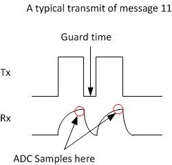
I am building an optical OOK (On off Key Ring) system without a carrier frequency. [However I have a guard time in between symbols, so a consecutive "1" messages will result in a pulse train as opposed to DC, see image]. Essentially, the presence of signal indicates one and lack of it indicates zero. I have a precise clock that is syncs the receiver with transmitter. The system operates with a low SNR and I like to improve SNR using DSP techniques.

I have a few questions:

I do selective sampling in my hardware, in other words, I do not continuously sample the channel but only sample when the probability of seeing the signal is maximum (i.e. this is a light pulse, I time the ADC such that ADC samples at the end of the pulse where I know the whole analog chain is stabilized).

This is particularly a low signal system and primary noise sources are shot noise, johnson noise and amplifiers internal noise.

I now use a simple threshold comparison in software to determine if the data is one or zero. Is there a better way? I have thought of some options but I like to hear from the experts.

So far I have considered the following options:

* Do continuous ADC and try to integrate during rise time:Not entirely sure on the benefit (There may be other benefits, I don't know).

* Matched filter in software: Don't really understand the math but based on what I read, a possibility

* Sample during the guard time and subtract this from the signal ADC value (This may provide some further details but also not so sure, guard time would be the noise measurement)

* Change hardware to a synchronous decoder, costly, time consuming and may not work well since my data rate is fast and getting a synchronous demodulator would mean expensive board since I have to built a multi-MHz carrier frequency system.
 

Firstly, I am no expert at this. but it looks like you have coherent Tx/Rx communication system.
Do you when the light pulse occurs exactly? (if you do: then it would be a determined system and there is no need for any likelihood detection)

i) Integration, is possibly better consider threshold detection is like peak detection. An rms detection would provide a more accurate result in this case. e.g., if there was an small output error it would still be ok,since your not considering single sampled values. but you have to consider the timeframe over which your integrating the signal.

ii)matched filter, is used a lot in digtal filtering, it is essentially convolving the output signal with the expected output pulse shape to maximize snr. This requires you to sample the output atleast the Nyquist rate.

iii) samples in the guard time? Normally the guard time is to avoid current signal from having any impact on the subsequent sample. So I am not sure of the impact.

Improving noise of the system can be done through various means, a typical method is by using error correction codes, though I doubt you need a complicated code for this but if your SNR is low, I would suggest encoding to start with a 1/2 convolutional code to start with. This implies your data rate doubles but your SNR will improve by using a simple ML(Viterbi) detection.
You can refer book by Shu Lin on ECC or Google!

Have Fun!
 

Thanks for the response. Couple of questions and clarifications. I have a deterministic system, in other words, I exactly know when the pulse will occur, there is no question about it.

Please see the image first.
69_1327904063.png


i. Integration: I am afraid there is a misunderstanding, look at the attached diagram. When I say integration, I mean, in the nano seconds preceeding the red circle, I am considering taking samples and summing them up. Without changing my hardware, I can basically get 3 adc samples during the rise time. (Alternatively, I can configure the ADC and let ADC capacitor to charge longer, which is an analog version of the same integration). If I want to make RMS detection, the way I imagine now is that I take as many ADC samples as possible in the signal time and do an RMS calculation. Is that what you are referring to?

ii. matched filter: In this case, (in traditional sense), my ADC rate is far below what is required by Nyquist, on top of that I am not fully sampling the stream, I am only sampling at the maximum likelihood point. But I can manually pad the data around my sample since I have an idea about how it should look, especially before and after the light pulse. Do you think this approach would work?

iii. Samples in guard time: The thinking is that the delta between the guard time and peak would act as some soft of high pass filter and remove or reduce the LF noise. (I am not a DSP guy, but intuitively, the LF noise will lift/pull all the pulses together, subtraction will equalize the baseline for all the pulse train and hence reduce the LF noise and boost SNR).

None of the channel coding/decoding would work in this special case (my application cannot accommodate any channel encoding), those are great suggestions.
 

i) if you hardware can support 3 samples, I would take all 3 samples and average it out for a better result. integration using a capacitor is a good idea but ensure the capacitor is able to discharge before the next data sample to avoid erroneous results compute the RC time delay for charge-discharge cycle in your circuit and keep that delay below the switching frequency of your input data.

ii) manual pad = interpolation. you can do that but since your not doing any baseband processing as such (i.e.DSP: no ECC, no filtering) i do not see too much use for it.

iii) The guard time is there to distinctly separate one sample from another, so I am not sure how sampling in the guard time is going to help. Sampling is typically done, where as you mentioned maximum likelihood(ML), you can possibly increase the number of sample at the ML point instead and average out, if you want a better estimate you can use the gradients between the three samples and decide on the signal output value as well.

Good luck
 

Regarding point #1:


- My hardware can support three samples, in this case, due to analog front end, even at the presence of strong signal, I shall see a curve rising, Do you think I could employ a matched filter?
Assume the whole pulse is 600nsec. I take three samples 200,400 and 600. Say these are x, y and z.

I use aX+bY+cZ polynomial to calculate the total value , where a would be something small 0.1, b should be larger say 0.5 and c would be 1. (Simply coefficients matching the rise time). Result of this polynomial would be compared to a threshold for decision. Would this be an accurate implementation of a better integration? (Something like a matched filter, don't know if this is matched filter but intuitively it makes sense to me)
 

the rationale you have is ok. the only thing with matched filtering is it involves convolution of your samples than a simple addition. The rationale is purely mathematical and can be found in any signal and systems book. You have created 3 weights which are like your filter coefficients (a,b,c).
Now you are filtering your input so in the time domain so you will need to convolve to get the max. SNR. Convolve the signal with your filter , where you normalize your filter coefficients by dividing by the 2-norm of the filter so that the convolved output is correct. The principle is you should have a unit output convolving the input signal with the matched filter, providing you with the optimum output.
 

I did some research after I wrote the earlier message. I am trying to get a sense of what exactly is the operation I need to perform and I think following is the method. Please let me know your feedback.

In time domain, lets assume x1, x2 and x3 are my samples. Matched filtering is convolving this with a symmetrical but time shifted signal.

So let's define that signal as y1, y2, y3 (y1 is 1, y2 is 0.7 and y3 is 0.2, similar in shape to our signal, only symmetric)

After that:

t0 = x1*y1
t1 = x1*y2+y1*x2
t2 = x1*y3+x2*y2+x3*y1
t3 = x2*y3+x3*y2
t4= x3*y3

This is the full convolution. Than I take the maximum value and use that as my comparator input. Does this make sense?
 

Looks reasonable, using the mx is one possiblity the other being using the 2-norm of the matched filter.

Have Fun!
 

Status
Not open for further replies.

Similar threads

Part and Inventory Search

Welcome to EDABoard.com

Sponsor

Back
Top