Continue to Site

Welcome to EDAboard.com

Welcome to our site! EDAboard.com is an international Electronics Discussion Forum focused on EDA software, circuits, schematics, books, theory, papers, asic, pld, 8051, DSP, Network, RF, Analog Design, PCB, Service Manuals... and a whole lot more! To participate you need to register. Registration is free. Click here to register now.

Circuit works, but how?

Status
Not open for further replies.

Negativ3s

Newbie level 3
Joined
Dec 9, 2011
Messages
3
Helped
0
Reputation
0
Reaction score
0
Trophy points
1,281
Activity points
1,300
Namur.jpg

Hi forumers!

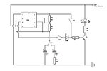
I have this cct that triggers the input to a counter/timer at frequency set by C1 & c2/R1 and SW3. Can someone explain to a noob HOW this thing works?

The circuit triggers by pushing momentary switch SW1, and provides continuous pulses. Momentary switch SW2 provides a single pulse.

Thanks a lot.
 

The circuit is incomplete. IC pin No.8, R3(?)* and SW2 have to be connected to the +12V line. Other than that, the operation is quite simple.

Pressing SW2 connects R5 to +12V and supplies current to T1 base through R5, turning it and the LED on. This operation does not involve the rest of the circuit.

IC1, R3(?)*, R4, C1, C4 make up a classic astable multivibrator (MV) which generates a contiuous stream of on-off pulses. The MV keeps running as long as it receives power. SW1 simply acts to connect the output of the MV to T1 which in turn drives the LED.

*This looks like an "R3" on the diagram but there's another R3 at T1's collector. It's probably meant to be R2.

I don't immediately see a need for R1. C1 and C2 do not have to be polarised types, i.e. with + and - terminals.

Pjdd, you have helped a lot, many thanks.

Ok, is it possible to design the output stage to be a dummy namur switch, and operate the input stage of a switch amplifier properly? (instead of lighting up an LED.

Spec of the switch amp is as follows:
Open circuit voltage of approx 8V DC
Short-circuit current 8 mA
Switching point 1.2 ... 2.1 mA
switching hysteresis 0.2 mA

Some guidance on the design theory is what I'm after here. Many thanks again.
 

Ok, cracked it by using a simple Avago Solid State Relay. Works beautifully.
 

Status
Not open for further replies.

Part and Inventory Search

Welcome to EDABoard.com

Sponsor

Back
Top