Continue to Site

Welcome to EDAboard.com

Welcome to our site! EDAboard.com is an international Electronics Discussion Forum focused on EDA software, circuits, schematics, books, theory, papers, asic, pld, 8051, DSP, Network, RF, Analog Design, PCB, Service Manuals... and a whole lot more! To participate you need to register. Registration is free. Click here to register now.

Looking for some basic help/understanding of the use/design of a toroidal transformer

Status
Not open for further replies.

Gilligan8

Newbie level 4
Joined
Nov 9, 2011
Messages
5
Helped
0
Reputation
0
Reaction score
0
Trophy points
1,281
Activity points
1,338
I have a conveyor dryer for screen printing and it has 3 heater panels that are wired in parallel to a distro block.

They are 220v drawing about 12+ amps. One of these has a temp probe in it and has a readout on my panel. The problem is that if one of the other 2 go out, I have no way of knowing and it can really ruin a job and not cure the shirts properly. Right now the only way I can tell is I check to make sure the panels are heating up (by touching) when I start the dryer up. Then after I'm done with a job I shoot the panels with a infrared temp gun to make sure they are still hot. Not really ideal at all.

So, my idea is to drive some LED's off the leads going to each panel via a toroidal transformer. I will at least see if they all light up together while they panels are in their on cycle (obviously they cycle to stay at X temp) or if one of them has failed.

So as a proof of concept I grabbed a clip on core and wrapped a bit of solid core telephone cable and wrapped it. I then clipped it on a lead and turned it on then checked for voltage with my fieldpiece meter (granted kind of crude, possibly only measures down to a 10th of a volt)... but I got ZILCH... not even .1v.

Here is a pic of my admittedly VERY week proof of concept transformer.
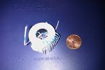
IMAG0136.jpg

Am I just not putting enough into the windings or am I barking up the wrong tree entirely?
 

If you want to drive led's from house current at low cost and fewest parts, then there's a clever way of using a capacitor to drop the voltage.

Since it's done by reactance (not resistance), it generates no heat.

LED flashers, Line powered LEDs, LED Traffic lights

You'll need to alter values to suit 220 VAC.
 

It's not clear, why the heaters are apparently failing quite often. I guess, with a good design, this can be expected after several yeasr of operation. Your selfmade current transformer doesn't work, because clip-on cores or low-permeability ferrite, designed for RF interference supression. Industry standard current transformers have usually tape-wound iron cores, or possibly low-frequency ferrites. You'll need a sensitive amplifier to detect the low voltage, or more turns. You didn't mention, how you exactly wanted to interface the indicator LED with the transformer output signal.
 

@Brad, COMPLETELY aware that I need to do more to drive an LED from a 220v source, but no sense in messing with that if I have a 0v source. I first NEED a source!

@FvM, It's not that they fail often (granted they all did fail just recently and I had to repair them... it's just some serious heat 900 degrees F... the connections eventually have enough and corrode out). The problem is I can't afford to have them fail at all. If they fail then the job fails and I have ZERO way to know (unless I constantly check). Right now I'm new to the business so I don't have steady jobs and it's not hard to check each time. But once things ramp up, I SHOULD be printing ALL day. I can be expected to check these panels constantly. I know of another guy that had Amp meters put on each one... but that's easier to ignore (and more expensive) than a lamp of some sort that is easy to know (on or off) at a glance. He put those meters in on his dryer because of having to eat one failed job... didn't want this to happen to him again.

Back to task at hand... So yeah, I used what I had laying around. I'm sure I can find or grab another core if you think this is probably the problem. I never planned on using a clamp on style because obviously there are not going to be as good (sacrifice performance for ease of use), it was just something I had.

I was hoping that I would be able to drive the LED straight off the transformer would some basic cap/resistor/diode setup. My lead is stranded 10 gauge (maybe 8), what would you suggest I get for a core and what do you suggest I use for the windings?
 

Your idea is basically sound. However, if you can't find a toroid whose properties are designed for low (mains) frequencies, why not use an ordinary low power transformer (with E and I laminations)? Strip off the original windings and put on your own.
 
Last edited:

Sorry, I wasn't sure what you wanted. You want to verify that an element is carrying current by lighting an led.

It's worth a try to use this method.

I once wanted to detect when a refrigerator came on.

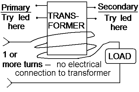
I had success by wrapping about 3-4 turns of the current-carrying wire around a transformer. I had to use only one of the AC wires. (You probably know that wrapping both AC wires would negate the magnetic field.)

This is not typical use of a transformer. I was trying a sort of inductive coupling.

I hooked up an led across the windings. I tried the primary winding. And the secondary.

One of them provided enough current to make the led light.

The other winding was not hooked up to anything.

I believe it worked with the first transformer I tried. Again it was a matter of inductive coupling, rather than to step voltage up or down.

It probably will work best to use one which does not have metal shielding around the windings.
 

Ok... so I'm sort of following you guys.

Anyone care to explain a little further? Pics would help too. :)

I've got enough wires to wrap a few turns around a transformer so that idea is possible.
 

This is what worked for me. The refrigerator was drawing only a few amps. The led was dim. You might get better results since you're drawing 12 amps. It may take some experimenting.

84_1320906458.gif


---------- Post added at 02:12 ---------- Previous post was at 00:30 ----------

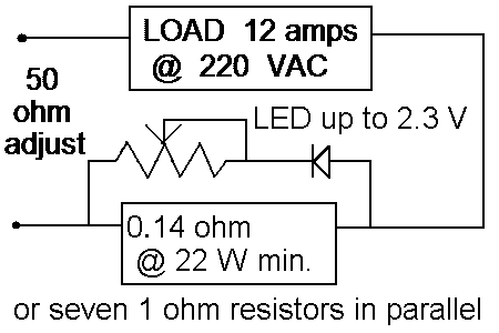
Just in case this is the easier way to go. I found that a .14 ohm shunt will drop sufficient volts to power an LED.

This is based on 12 A going through it. The LED lights briefly during one half of the cycle.

The resistor (or network of resistors in parallel) should have a total rating at twice the 22W figure. Radio Shack does (or did) carry 1 ohm resistors rated 10W each.

A heater element changes resistance between its cold and hot states. Therefore it's wise not to drive the LED with overmuch current. The led should have some inline resistance to bring the average current down to 10 mA or so. Try various values under 50 ohms.

25_1320912462.gif
 

Trying to follow that second schematic.

This would be splicing inline with my heater? I'm trying to avoid that because that would be adding a point of failure and I like keeping things as simple as they are (which in this case is pretty simple... mercury switch that sends mains to elements)

---------- Post added at 12:50 ---------- Previous post was at 12:50 ----------

Oh, any specifics on what kind of transformer I could use for the 1st option?
 

I think I'm getting it finally. You want 3 led's to light up for three elements.

Since it's AC you can't just lay a compass on top of the wire.

If you want to use a simple method, then it involves splicing in something or other.

This means you'll need to add an extra foot or two of wire, unless you already have enough slack to wind a few turns around a transformer.

You'll need 3 transformers. I suppose these can be most any type. There should only be paper or plastic covering the windings. If it's covered by a metal housing then it may not work.

Will it work with inexpensive small transformers? It's unpredictable.

There's even a chance you would have success with other kinds of coils. If it has a ferrite in the center then remove the ferrite, and run your current-carrying wire down the empty middle. (This appears similar to what you were trying in the first place.) Don't know if RF coils will produce sufficient voltage when used with 50-60 Hz, however.

As for the shunt resistor method...

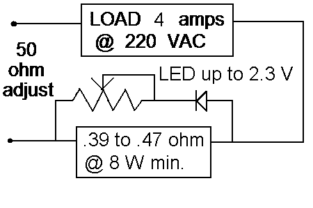
To use a shunt resistor with one 4 A element, you would change the value to somewhere between .39 and .47 ohm.

If you were to use .33 ohm ( three 1 ohm in parallel) then you may or may not get sufficient voltage across your led.

It's okay to use .5 ohm (two 1 ohm in parallel) as long as components are beefy enough to withstand the increased power dissipation. Whatever you use, rate it for a total 20W and that will be ample.

You'll need 3 of this.

9_1320959644.gif
 

Ok... I'll grab some transformers and see what I can come up with.

Actually EACH panel draws 12.x amps... so your first shunt diagram was still valid. As you can see I have plenty of juice to pull from via a transformer method... I just need to find one that will do it.
 

I would prefer a self made regular current transformer, e.g. 1:500 turns corresponding to 12A:24mA current ratio. A small core like EI30 has about 1 cm² cross section which is good for up to 12V output voltage at 50 Hz (42 turns*cm²/V). So you can easily supply a LED through a bridge rectifier.
 

Status
Not open for further replies.

Part and Inventory Search

Welcome to EDABoard.com

Sponsor

Back
Top