zmcddn
Newbie level 4
Dear all,
I was working with the Mur's first order and second order ABCs for the 2D FDTD programming.
There is a very strange problem happening right now.
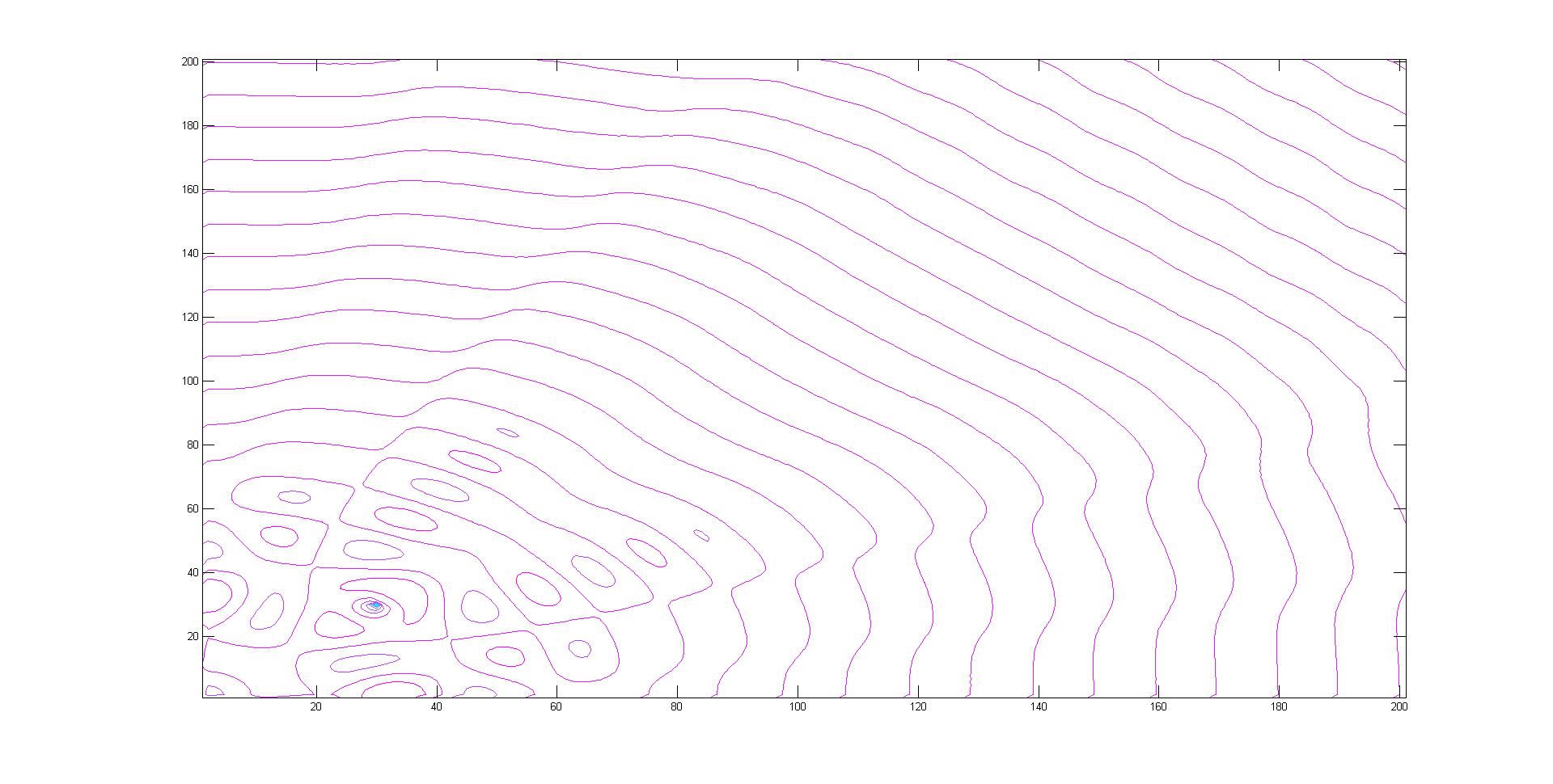
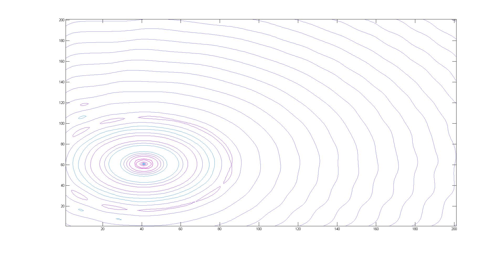
For BOTH the first order AND the second order Mur's ABC in my code, they only work for the upper and right boundaries, not for the top and bottom boundaries.
The top and bottom boundaries cannot absorb the wave somehow!
Could anyone help me with this?
I've been working on this problem for days and cannot figure out what is happening.
Thank you in advance!
---------- Post added at 23:06 ---------- Previous post was at 23:04 ----------
well, cannot upload file, says file invalid somehow. I'll just paste my file here.
clear all;
%Initialize matrices
Nx=201;
Ny=201;
N=500;
c=3e8;
dx=0.0005;
dy=0.0005;
dt=1/(c*sqrt((1/dx)^2+(1/dy)^2));
f=30e9;
epo=8.85419*10^-12;
epr=1;
mu=4*pi*10^-7;
Ez=zeros(Nx,Ny,N);
Hx=zeros(Nx,Ny,N);
Hy=zeros(Nx,Ny,N);
A=(c*dt-dx)/(c*dt+dx);
B=(2*dx)/(c*dt+dx);
C=((c*dt)^2)*dx/(2*(c*dt+dx)*dy^2);
R=(c*dt - dx)/(c*dt + dx);
for n=2:N
for i=2:Nx-1
for j=2:Ny-1
if ((i==30)&&(j==30))
Ez(i,j,n+1)=sin(2*pi*f*n*dt); %source
else
Hx(i,j,n+1)=Hx(i,j,n)-dt/(mu*dy)*(Ez(i,j+1,n)-Ez(i,j,n));
Hy(i,j,n+1)=Hy(i,j,n)+dt/(mu*dx)*(Ez(i+1,j,n)-Ez(i,j,n));
Ez(i,j,n+1)=Ez(i,j,n)+dt/(epo*epr*dx)*(Hy(i,j,n+1)-Hy(i-1,j,n+1))-dt/(epo*epr*dy)*(Hx(i,j,n+1)-Hx(i,j-1,n+1));
end
end
end
clear i; clear j;
%Boundary conditions
for j=2:Ny-1
Ez(Nx,j,n+1) = Ez(Nx-1,j,n) + R*(Ez(Nx-1,j,n+1) - Ez(Nx,j,n)); %right boundary
%Ez(Nx,j,n+1)=-Ez(Nx-1,j,n-1)+A*(Ez(Nx,j,n-1)+Ez(Nx-1,j,n+1))+B*(Ez(Nx,j,n)+Ez(Nx-1,j,n))+C*(Ez(Nx,j+1,n)-2*Ez(Nx,j,n)+Ez(Nx,j-1,n)+Ez(Nx-1,j+1,n)-2*Ez(Nx-1,j,n)+Ez(Nx-1,j-1,n));
Ez(1,j,n+1) = Ez(2,j,n) + R*(Ez(2,j,n+1)-Ez(1,j,n)); %left boundary
%Ez(1,j,n+1)=-Ez(2,j,n-1)+A*(Ez(1,j,n-1)+Ez(2,j,n+1))+B*(Ez(1,j,n)+Ez(2,j,n))+C*(Ez(1,j+1,n)-2*Ez(1,j,n)+Ez(1,j-1,n)+Ez(2,j+1,n)-2*Ez(2,j,n)+Ez(2,j-1,n));
end
for i=2:Nx-1
Ez(i,Ny,n+1) = Ez(i,Ny-1,n) + R*(Ez(i,Ny-1,n+1) - Ez(i,Ny,n)); %top boundary
%Ez(i,Ny,n+1)=-Ez(i,Ny-1,n-1)+A*(Ez(i,Ny,n-1)+Ez(i,Ny-1,n+1))+B*(Ez(i,Ny,n)+Ez(i,Ny-1,n))+C*(Ez(i+1,Ny,n)-2*Ez(i,Ny,n)+Ez(i-1,Ny,n)+Ez(i+1,Ny-1,n)-2*Ez(i,Ny-1,n)+Ez(i-1,Ny-1,n));
Ez(i,1,n+1) = Ez(i,2,n) + R*(Ez(i,2,n+1) - Ez(i,1,n)); %bottom boundary
%Ez(i,1,n+1)=-Ez(i,2,n-1)+A*(Ez(i,1,n-1)+Ez(i,2,n+1))+B*(Ez(i,1,n)+Ez(i,2,n))+C*(Ez(i+1,1,n)-2*Ez(i,1,n)+Ez(i-1,1,n)+Ez(i+1,2,n)-2*Ez(i,2,n)+Ez(i-1,2,n));
end
% Boundary conditions for four corner nodes
Ez(1,1,n+1)=.5*(Ez(1,2,n+1)+Ez(2,1,n+1));
Ez(Nx,1,n+1)=.5*(Ez(Nx-1,1,n+1)+Ez(Nx,2,n+1));
Ez(1,Ny,n+1)=.5*(Ez(1,Ny-1,n+1)+Ez(2,Ny,n+1));
Ez(Nx,Ny,n+1)=.5*(Ez(Nx-1,Ny,n+1)+Ez(Nx,Ny-1,n+1));
x=(0:0.05:10);
y=(0:0.05:10);
mesh(x,y,Ez") ,:,n+1));
,:,n+1));
axis([0 10 0 10 -1 1]);
pause(0.001);
end
thanks again
I was working with the Mur's first order and second order ABCs for the 2D FDTD programming.
There is a very strange problem happening right now.
For BOTH the first order AND the second order Mur's ABC in my code, they only work for the upper and right boundaries, not for the top and bottom boundaries.
The top and bottom boundaries cannot absorb the wave somehow!
Could anyone help me with this?
I've been working on this problem for days and cannot figure out what is happening.
Thank you in advance!
---------- Post added at 23:06 ---------- Previous post was at 23:04 ----------
well, cannot upload file, says file invalid somehow. I'll just paste my file here.
clear all;
%Initialize matrices
Nx=201;
Ny=201;
N=500;
c=3e8;
dx=0.0005;
dy=0.0005;
dt=1/(c*sqrt((1/dx)^2+(1/dy)^2));
f=30e9;
epo=8.85419*10^-12;
epr=1;
mu=4*pi*10^-7;
Ez=zeros(Nx,Ny,N);
Hx=zeros(Nx,Ny,N);
Hy=zeros(Nx,Ny,N);
A=(c*dt-dx)/(c*dt+dx);
B=(2*dx)/(c*dt+dx);
C=((c*dt)^2)*dx/(2*(c*dt+dx)*dy^2);
R=(c*dt - dx)/(c*dt + dx);
for n=2:N
for i=2:Nx-1
for j=2:Ny-1
if ((i==30)&&(j==30))
Ez(i,j,n+1)=sin(2*pi*f*n*dt); %source
else
Hx(i,j,n+1)=Hx(i,j,n)-dt/(mu*dy)*(Ez(i,j+1,n)-Ez(i,j,n));
Hy(i,j,n+1)=Hy(i,j,n)+dt/(mu*dx)*(Ez(i+1,j,n)-Ez(i,j,n));
Ez(i,j,n+1)=Ez(i,j,n)+dt/(epo*epr*dx)*(Hy(i,j,n+1)-Hy(i-1,j,n+1))-dt/(epo*epr*dy)*(Hx(i,j,n+1)-Hx(i,j-1,n+1));
end
end
end
clear i; clear j;
%Boundary conditions
for j=2:Ny-1
Ez(Nx,j,n+1) = Ez(Nx-1,j,n) + R*(Ez(Nx-1,j,n+1) - Ez(Nx,j,n)); %right boundary
%Ez(Nx,j,n+1)=-Ez(Nx-1,j,n-1)+A*(Ez(Nx,j,n-1)+Ez(Nx-1,j,n+1))+B*(Ez(Nx,j,n)+Ez(Nx-1,j,n))+C*(Ez(Nx,j+1,n)-2*Ez(Nx,j,n)+Ez(Nx,j-1,n)+Ez(Nx-1,j+1,n)-2*Ez(Nx-1,j,n)+Ez(Nx-1,j-1,n));
Ez(1,j,n+1) = Ez(2,j,n) + R*(Ez(2,j,n+1)-Ez(1,j,n)); %left boundary
%Ez(1,j,n+1)=-Ez(2,j,n-1)+A*(Ez(1,j,n-1)+Ez(2,j,n+1))+B*(Ez(1,j,n)+Ez(2,j,n))+C*(Ez(1,j+1,n)-2*Ez(1,j,n)+Ez(1,j-1,n)+Ez(2,j+1,n)-2*Ez(2,j,n)+Ez(2,j-1,n));
end
for i=2:Nx-1
Ez(i,Ny,n+1) = Ez(i,Ny-1,n) + R*(Ez(i,Ny-1,n+1) - Ez(i,Ny,n)); %top boundary
%Ez(i,Ny,n+1)=-Ez(i,Ny-1,n-1)+A*(Ez(i,Ny,n-1)+Ez(i,Ny-1,n+1))+B*(Ez(i,Ny,n)+Ez(i,Ny-1,n))+C*(Ez(i+1,Ny,n)-2*Ez(i,Ny,n)+Ez(i-1,Ny,n)+Ez(i+1,Ny-1,n)-2*Ez(i,Ny-1,n)+Ez(i-1,Ny-1,n));
Ez(i,1,n+1) = Ez(i,2,n) + R*(Ez(i,2,n+1) - Ez(i,1,n)); %bottom boundary
%Ez(i,1,n+1)=-Ez(i,2,n-1)+A*(Ez(i,1,n-1)+Ez(i,2,n+1))+B*(Ez(i,1,n)+Ez(i,2,n))+C*(Ez(i+1,1,n)-2*Ez(i,1,n)+Ez(i-1,1,n)+Ez(i+1,2,n)-2*Ez(i,2,n)+Ez(i-1,2,n));
end
% Boundary conditions for four corner nodes
Ez(1,1,n+1)=.5*(Ez(1,2,n+1)+Ez(2,1,n+1));
Ez(Nx,1,n+1)=.5*(Ez(Nx-1,1,n+1)+Ez(Nx,2,n+1));
Ez(1,Ny,n+1)=.5*(Ez(1,Ny-1,n+1)+Ez(2,Ny,n+1));
Ez(Nx,Ny,n+1)=.5*(Ez(Nx-1,Ny,n+1)+Ez(Nx,Ny-1,n+1));
x=(0:0.05:10);
y=(0:0.05:10);
mesh(x,y,Ez
,:,n+1));axis([0 10 0 10 -1 1]);
pause(0.001);
end
thanks again