Welcome to our site! EDAboard.com is an international Electronics Discussion Forum focused on EDA software, circuits, schematics, books, theory, papers, asic, pld, 8051, DSP, Network, RF, Analog Design, PCB, Service Manuals... and a whole lot more! To participate you need to register. Registration is free. Click here to register now.
hi,
here i am using a 28vdc voltge at center tap of primary,as far as i know the voltage at top switch wrt to center tap should be +28v-0v.but the voltage is +/-28v.
plz explain me.
There are at least 3 output pins from a center tap transformer. We have the + lead, the - lead and the center tap. Depending on what you want you can get. The + and center tap gives you +28 - 0v. the - and center tap gives you -28 and 0v, the + and - gives you +28 and -28V which is equivalent to +56 0v. your connection works on the third case which I suspect is not your design. So you may alter your design to use one of the first 2 cases or buy a 14v - 0 - 14v center tap transformer
Your observation is correct. Each end of primary will be +/- 28 volts with respect to center tap.
Primary winding acts as autotransformer, so with +28vdc on center tap, when one end goes low the other end goes to twice the center tap voltage (56 volts). (minus whatever MOSFET On state Vds voltage drop is for given Ids current).
Why do you need bidirectional switches on secondary?
The circuit is prone to DC core bias buildup on transformer without some mitigating correction.
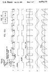
O.K., I understand the phase modulation idea. Basically, it's another way to implement a sine PWM. I assume, the ramp voltage range is -2V to +2V? Personally I would prefer a more reliable method than clocking the DFF with the comparator output, but it should work if designed properly. Any questions left?
This site uses cookies to help personalise content, tailor your experience and to keep you logged in if you register.
By continuing to use this site, you are consenting to our use of cookies.