Continue to Site

Welcome to EDAboard.com

Welcome to our site! EDAboard.com is an international Electronics Discussion Forum focused on EDA software, circuits, schematics, books, theory, papers, asic, pld, 8051, DSP, Network, RF, Analog Design, PCB, Service Manuals... and a whole lot more! To participate you need to register. Registration is free. Click here to register now.

Help me please...regarding Advanced design system

Status
Not open for further replies.

sujamenon

Newbie level 2
Joined
Sep 1, 2011
Messages
2
Helped
0
Reputation
0
Reaction score
0
Trophy points
1,281
Location
India
Activity points
1,293
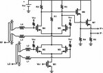
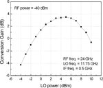
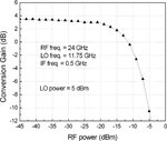
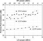
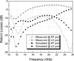
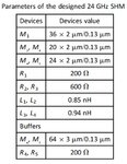
Hello everyone...I have been given an assignment project in mixer design using Advanced design system...But since I'm totally new to ADS,I have no idea how to start up my project...Can u all please help me and guide me please??I have attached my reference diagram and its graphs..can anyone please tell me how to set the parameters of M1,M2 etc.. on the schematic window as given in the table and what type of simulation should i do to get the output graphs as obtained in the paper(i.e port isolation and losses plot)....please...i appreciate any kind of help.
 

Attachments

  • design.jpg
    design.jpg
    66.5 KB · Views: 92
  • gain_vs_lo_pwr.jpg
    gain_vs_lo_pwr.jpg
    48.3 KB · Views: 82
  • gain_vs_pwr.jpg
    gain_vs_pwr.jpg
    51.4 KB · Views: 75
  • isolation.jpg
    isolation.jpg
    57.7 KB · Views: 73
  • losses.jpg
    losses.jpg
    62.6 KB · Views: 74
  • parameters.jpg
    parameters.jpg
    64 KB · Views: 76

I think the easiest way to proceed is to start from some example already available in ADS; a good one to start from is MixerDiffMode.

From the ReadMe:
This example shows how to simulate a differential-mode Gilbert cell mixer.
Many RFIC circuits have differential-mode inputs and outputs, so this
example should be of interest to RFIC designers. Small-signal mixer
mode is also used here, which is a technique that allows the conversion
gain to be calculated quickly, when the RF signal is assumed to be
small enough not to drive the mixer into compression. A noise figure
simulation is also included.


Just open the example and replace the existing circuit with the one of your project, using proper model for the MOS (a similar one is already available for the BJTs).


Then you can use the same bench modifying the setting of HB, adding parameters and so on.

With a simple add you can do S-parameter also, sweep the LO power.

I hope it can help.

Mazz
 
Status
Not open for further replies.

Part and Inventory Search

Welcome to EDABoard.com

Sponsor

Back
Top