Continue to Site

Welcome to EDAboard.com

Welcome to our site! EDAboard.com is an international Electronics Discussion Forum focused on EDA software, circuits, schematics, books, theory, papers, asic, pld, 8051, DSP, Network, RF, Analog Design, PCB, Service Manuals... and a whole lot more! To participate you need to register. Registration is free. Click here to register now.

MikroC & SD CARD & PIC18F4520

Status
Not open for further replies.
Try this, it may help

extern sfr sbit Mmc_Chip_Select at RC0_bit;
extern sfr sbit Mmc_Chip_Select_Direction at TRISC0_bit;

Nope, still the same. Why you want change to RC0 ? I'm using PIC18F4520 , which PORT C pin 2 is CS .
Anyone know why this error occur ?

---------- Post added at 20:56 ---------- Previous post was at 19:46 ----------

0 1 mikroCPIC1618.exe -MSF -DBG -pP18F4520 -DL -O11111114 -fo10 -N"C:\Users\User\Desktop\MikroC testing\MMC.mcppi" -SP"C:\Program Files (x86)\Mikroelektronika\mikroC PRO for PIC\defs\" -SP"C:\Program Files (x86)\Mikroelektronika\mikroC PRO for PIC\uses\P18\" -SP"C:\Users\User\Desktop\MikroC testing\" "MMC.c" "__Lib_Math.mcl" "__Lib_MathDouble.mcl" "__Lib_System.mcl" "__Lib_Delays.mcl" "__Lib_Button.mcl" "__Lib_SPI_c345.mcl" "__Lib_UART_c67.mcl" "__Lib_Mmc.mcl" "__Lib_MmcFat16.mcl"
0 125 All files Preprocessed in 32 ms
0 121 Compilation Started MMC.c
22 122 Compiled Successfully MMC.c
0 126 All files Compiled in 78 ms
0 359 Unresolved extern 'islower' __Lib_MmcFat16.c
0 359 Unresolved extern 'toupper' __Lib_MmcFat16.c
0 359 Unresolved extern 'islower' __Lib_MmcFat16.c

0 0
0 102 Finished (with errors): 03 Sep 2011, 15:46:44 MMC.mcppi

Those problem has been solved by including C_type library. =)

But right now I'm still have problem intializing and write a file to sd card.
 
Last edited:
Nope because I dont have any uart hardwares on my side.
That's why I rewrite it by displaying out by 16x2 LCD (last few replies I posted ago) or simple code declaration (right now).
Both are not working properly.
 

I mean try to compile the example from mickroC if there is no error then add the LCD code or you may want to create your LCD code in separate project and make it sure it will work and then combine the two LCD + your SD card project..

in this way you can easily what side of your code that is causing an error
 

Hi guys,
I have remodified the code from user manual MMC's example by interfacing to my 16x2 LCD instead UART.

Code:
sbit Mmc_Chip_Select           at LATC0_bit;  // for writing to output pin always use latch (PIC18 family)
sbit Mmc_Chip_Select_Direction at TRISC0_bit;
// eof MMC module connections

sbit LCD_RS at RB4_bit;
sbit LCD_EN at RB5_bit;
sbit LCD_D7 at RB3_bit;
sbit LCD_D6 at RB2_bit;
sbit LCD_D5 at RB1_bit;
sbit LCD_D4 at RB0_bit;

// Pin direction
sbit LCD_RS_Direction at TRISB4_bit;
sbit LCD_EN_Direction at TRISB5_bit;
sbit LCD_D7_Direction at TRISB3_bit;
sbit LCD_D6_Direction at TRISB2_bit;
sbit LCD_D5_Direction at TRISB1_bit;
sbit LCD_D4_Direction at TRISB0_bit;


// Variables for MMC routines
unsigned char SectorData[512];        // Buffer for MMC sector reading/writing
unsigned char data_for_registers[16]; // buffer for CID and CSD registers

// UART1 write text and new line (carriage return + line feed)
/*
void UART1_Write_Line(char *uart_text) {
  UART1_Write_Text(uart_text);
  UART1_Write(13);
  UART1_Write(10);
}
  */
// Display byte in hex
void PrintHex(unsigned char i) {
  unsigned char hi,lo;

  hi = i & 0xF0;               // High nibble
  hi = hi >> 4;
  hi = hi + '0';
  if (hi>'9') hi=hi+7;
  lo = (i & 0x0F) + '0';       // Low nibble
  if (lo>'9') lo=lo+7;

// UART1_Write(hi);
// UART1_Write(lo);
}

void main() {

  const char   FILL_CHAR = 'm';
  unsigned int i, SectorNo;
  char         mmc_error;
  bit          data_ok;

  ADCON1 |= 0x0F;                  // Configure AN pins as digital
  CMCON  |= 7;                     // Turn off comparators
  TRISB = 0;
  PORTB = 0xFF;

  Delay_ms(2500);

// UART1_Write_Line("PIC-Started"); // PIC present report


  // Initialize SPI1 module
  SPI1_Init_Advanced(_SPI_MASTER_OSC_DIV64, _SPI_DATA_SAMPLE_MIDDLE, _SPI_CLK_IDLE_LOW, _SPI_LOW_2_HIGH);
  Lcd_Init();                                   // Initialize GLCD

  Lcd_Out(1,1,"PIC-STARTED");
  Delay_ms(2000);
  Lcd_Cmd(_LCD_CLEAR);
  
  // initialise a MMC card
  mmc_error = Mmc_Init();
  if(mmc_error == 0)
     Lcd_Out(2,1,"MMC INIT OK");
  else
     Lcd_Out(2,1,"MMC INIT ERROR");


  // Fill MMC buffer with same characters
  for(i=0; i<=511; i++)
    SectorData[i] = FILL_CHAR;

  // Choose sector
  SectorNo = 590;

  // Write sector
  mmc_error = Mmc_Write_Sector(SectorNo, SectorData);
  if(mmc_error == 0)
//    UART1_Write_Line("Write-OK");
     Lcd_Out(1,1,"WRITE OK");

  else  // if there are errors.....
    //UART1_Write_Line("Write-Error");
     Lcd_Out(1,1,"Write ERROR");
     Delay_ms(5000);

  // Reading of CID register
  mmc_error = Mmc_Read_Cid(data_for_registers);
  if(mmc_error == 0) {
   // UART1_Write_Text("CID : ");
    Lcd_Out(2,1,"CID");

    for(i=0; i<=15; i++)
      PrintHex(data_for_registers[i]);
   // UART1_Write_Line("");
  }
  else
  //  UART1_Write_Line("CID-error");
      Lcd_Out(2,1,"CID-ERROR");

  // Reading of CSD register
  mmc_error = Mmc_Read_Csd(data_for_registers);
  if(mmc_error == 0) {
  //  UART1_Write_Text("CSD : ");
      Lcd_Out(1,1,"CSD: ");
    for(i=0; i<=15; i++)
      PrintHex(data_for_registers[i]);

//   UART1_Write_Line("");
  }
  else
//   UART1_Write_Line("CSD-error");
     Lcd_Out(1,1,"CSD-error");

  // Read sector
  mmc_error = Mmc_Read_Sector(SectorNo, SectorData);
  if(mmc_error == 0) {
    //UART1_Write_Line("Read-OK");
     Lcd_Out(1,1,"Read-ok");
    // Chech data match
    data_ok = 1;
    for(i=0; i<=511; i++) {
      //UART1_Write(SectorData[i]);
      if (SectorData[i] != FILL_CHAR) {
        data_ok = 0;
        break;
      }
    }

    //UART1_Write_Line("");
    if (data_ok)
//      UART1_Write_Line("Content-OK");
       Lcd_Out(1,1,"Content Ok");

    else
      //UART1_Write_Line("Content-Error");
        Lcd_Out(1,1," Content ERROR");
  }
  else  // if there are errors.....
    //UART1_Write_Line("Read-Error");
      Lcd_Out(1,1,"Read Error");
 //   Lcd_Cmd(_LCD_CLEAR);
  // Signal test end
  //UART1_Write_Line("Test End.");
      Delay_ms(5000);
    Lcd_Out(1,1,"Test End");
}

View attachment 61013

These'r my brief schematics diagram.
I have use multi-meter to measure the input of my SD card circuit which around 3.5-3.6V.
I have compiled & tested . The LCD just display MMC init Error & Write Error and didnt show until "Test End".

I have formatted my SD card 1GB with my windows 7(ulti) 64bits with following settings:
Fat (default), Allocation Size : Default

My mikroC PIC18f4520 oscillator value have tried 8 & 10 Mhz.

Any idea how to fix this ?
Sorry for lengthy above description.

This is 18th post replied I posted, which is the user manual example and re-modified into LCD compatible but still I have problem which mentioned above.
 

check your SD card connections.. the mikroc is working

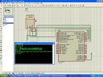
this should be the result in your LCD


check the image
 

Attachments

  • tae.JPG
    tae.JPG
    200.3 KB · Views: 131

check your SD card connections.. the mikroc is working

this should be the result in your LCD


check the image

Where should I connect my RC6& RC7 to ? I saw your diagram posted was connected to result icon ?
WoW, How can there is direct result come out from there ?
Is this some kind of simulation ?

Sorry for asking much question because I'm still new to MikroC compiler.

---------- Post added at 23:10 ---------- Previous post was at 23:09 ----------

check your SD card connections.. the mikroc is working

this should be the result in your LCD


check the image

Where should I connect my RC6& RC7 to ? I saw your diagram posted was connected to result icon ?
WoW, How can there is direct result come out from there ?
Is this some kind of simulation ?

Sorry for asking much question because I'm still new to MikroC compiler.
 

search proteus and you can download the trial version.proteus is a very good simulator

RC6 and RC7 is a uart PIN dont mind it because you dont have uart..

I suggest you to focus on sd card initialization and remove all codes for a while.. as soon as you got it working or the sd card detected then that's the time you add code for another function..

---------- Post added at 17:16 ---------- Previous post was at 17:13 ----------

monitor every value returned by every function in sd card routine..

read the manual of mikcroC what is the return of every function ..]

example if the initialization successful then it will return a 1 value then if it returns 1 then display in "lcd initialization complete" in your LCD..

debug it step by step

Your attachment result diagram, is it mikroC example code.

"Debug", are you referring the proteus simulation ?
 

Alright, I will update if any further problems arise.
Thank you, romel_emperado.

---------- Post added at 23:42 ---------- Previous post was at 23:41 ----------

Alright, I will update if any further problems arise.
Thank you, romel_emperado.
 

Regarding proteus simulation,

Can you provide link for me to learn how to setup a circuit such like your previous attachment shown before.
I have installed it.
 

I tried to build exactly the same example code provided in MikroC library files but unfortunately i am receiving logical and syntax errors.
 

I tried to build exactly the same example code provided in MikroC library files but unfortunately i am receiving logical and syntax errors.
what version of mikroC you are using.? but I dont believe the error is logical...
 

I have done several checking for my circuit and yet failed for initialization in the hardware.
However,I did simulation in Proteus which is working properly.

Code:
sfr sbit Mmc_Chip_Select at RC2_bit;
sfr sbit Mmc_Chip_Select_Direction at TRISC2_bit;
// MMC module connections

// Lcd pinout settings
sbit LCD_RS at RB4_bit;
sbit LCD_EN at RB5_bit;
sbit LCD_D7 at RB3_bit;
sbit LCD_D6 at RB2_bit;
sbit LCD_D5 at RB1_bit;
sbit LCD_D4 at RB0_bit;

// Pin direction
sbit LCD_RS_Direction at TRISB4_bit;
sbit LCD_EN_Direction at TRISB5_bit;
sbit LCD_D7_Direction at TRISB3_bit;
sbit LCD_D6_Direction at TRISB2_bit;
sbit LCD_D5_Direction at TRISB1_bit;
sbit LCD_D4_Direction at TRISB0_bit;

void main(){
 char mmc_error;
 ADCON1 = 0x0F;
 CMCON = 0x07;
 TRISB = 0;
 PORTB = 0xFF;

 
// Initialize SPI1 module and set pointer(s) to SPI1 functions
SPI1_Init_Advanced(_SPI_MASTER_OSC_DIV16, _SPI_DATA_SAMPLE_MIDDLE,_SPI_CLK_IDLE_LOW, _SPI_LOW_2_HIGH);
Lcd_init();
Lcd_out(2,1,"Test start");
Delay_ms(2000);

mmc_error = Mmc_Init();
if(mmc_error == 0)
Lcd_out(1,1,"MMC Init-OK"); // If MMC present report

else
Lcd_out(1,1,"MMC Init-error"); // If error report

Mmc_Fat_Assign("MIKROELE.TXT",0xA0);

}

What's the problem caused ??
Any idea ?
 

did you set the configuration bits of your device properly?

---------- Post added at 08:16 ---------- Previous post was at 08:15 ----------

post here your configuration bits setting..
 

did you set the configuration bits of your device properly?

---------- Post added at 08:16 ---------- Previous post was at 08:15 ----------

post here your configuration bits setting..

Configuration bits will be :
MMC part:
sfr sbit Mmc_Chip_Select at RC2_bit;
sfr sbit Mmc_Chip_Select_Direction at TRISC2_bit;
 

config bits are for the setting of your device to work properly.. it is where you select if you want to use external/internal clock.


read this file from mikcrochip website about config bits.

**broken link removed**

---------- Post added at 08:27 ---------- Previous post was at 08:25 ----------

check this link on how to set the config bits for mikro C

**broken link removed**
 

Status
Not open for further replies.

Part and Inventory Search

Welcome to EDABoard.com

Sponsor

Back
Top