Continue to Site

Welcome to EDAboard.com

Welcome to our site! EDAboard.com is an international Electronics Discussion Forum focused on EDA software, circuits, schematics, books, theory, papers, asic, pld, 8051, DSP, Network, RF, Analog Design, PCB, Service Manuals... and a whole lot more! To participate you need to register. Registration is free. Click here to register now.

learning to use MultiSim

Status
Not open for further replies.
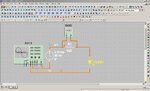
u can lock the tool bar. right click on tool bar and u will see the lock bar option.. just check on..

Hi A. Tech: It didn't work for me. I don't get lock toolbar option.

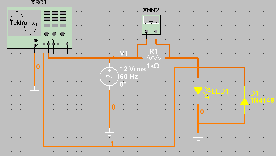
I would be surprised if the oscilloscope showed anything different, you have connected the input to gnd...

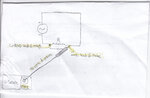
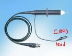
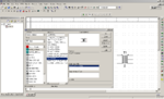
Hi Alex: I have attached the MS10 circuit drawing. I don't know how to connect the circuit to CH1 of the o-scope. In the lab I have seen they have a single wire probe to connect to CH1 or CH2. Please let me know what to do.
 

Attachments

  • Circuit2.rar
    78.6 KB · Views: 66

Here you have, I also add diode parallel to the LED. So now you can increase the input voltage.
 

Attachments

  • Circuit2x.rar
    173.3 KB · Views: 62
Last edited:

connectors 1,2,3,4 are the four inputs of the oscilloscope, connect them to the signal you want to see

Alex
 

Here you have, I also add diode parallel to the LED. So now you can increase the input voltage.

Jony, many thanks. It is very nice of you but unfortunately MS11's files don't open on MS10. Could you please send me a screenshot?

connectors 1,2,3,4 are the four inputs of the oscilloscope, connect them to the signal you want to see

Thanks, Alex. Aren't 1, 2, 3, 4 fours channels - two wires per channel? I have attached a screenshot. Please have a look to see if it's okay. I think it's not right.
 

Attachments

  • msoscopeprob.jpg
    msoscopeprob.jpg
    237.2 KB · Views: 62

No the four inputs are four independent channel inputs all referenced to the gnd, if you want to see a differential signal there is a math function between channel 1 and 2.

Alex
 

How do I cross two wires without making a junction between them?

Thank for the screenshot, Jony. Could you please correct the connection to the o-scope of the attached circuit? For some reason I found the circuit in your screenshot little confusing?

Regards
PG
 

What confuse you in the diagram??
The CH1 measure voltage between V1 and GND and CH2 measure voltage across the diodes.
 

I add the file to multisim10
 

Attachments

  • Circuit2a.rar
    515.8 KB · Views: 48

What confuse you in the diagram??
The CH1 measure voltage between V1 and GND and CH2 measure voltage across the diodes.

Thank you, Jony. Are you referring to the circuit which you added to MS10? If that's the case, then I think you wanted to say CH2 measures voltage between V1 and GRN (in other words, across R1), and CH1 measures voltage across the diode.

How do I cross two wires without making a junction between them?

Best wishes
PG
 
Last edited:

Thank you, Jony. Are you referring to the circuit which you added to MS10? If that's the case, then I think you wanted to say CH2 measures voltage between V1 and GRN (in other words, across R1), and CH1 measures voltage across the diode.
No, CH2 measure voltage between V1 (node 4) and GND so we are measuring voltage across the AC voltage source.
In the simulation using that scope it is impassible to measure in the same time the voltage across R1 and voltage across the diode.
Becaues we have only one GND terminal in the scope.

How do I cross two wires without making a junction between them?
When you you draw the wire simply don't click the mouse when two wires crossed.
 

Attachments

  • Circuit2b.rar
    45.3 KB · Views: 44
  • Like
Reactions: PG1995

    PG1995

    Points: 2
    Helpful Answer Positive Rating
No, CH2 measure voltage between V1 (node 4) and GND so we are measuring voltage across the AC voltage source.
In the simulation using that scope it is impassible to measure in the same time the voltage across R1 and voltage across the diode.
Becaues we have only one GND terminal in the scope.


When you you draw the wire simply don't click the mouse when two wires crossed.

Thank you, Jony.. I have been learning a lot from you. This is the truth I don't like this technical stuff but having you and others members there makes it somewhat interesting...

1: We can use CH3 to measure voltage across R1. Can't we?

2: I also have UItiboard software along with MultiSim. What is it used for?

3: I don't think we use o-scope this way in the lab (at least I haven't seen it being used that way). Please see the attached diagrams to see how I have seen it used. Nothing is attached to the GRND terminal on the o-scope.

The o-scope which I have seen being used:
https://img8.imageshack.us/img8/5408/oscillo.jpg
 

Attachments

  • oscopeinlab.jpg
    oscopeinlab.jpg
    584.9 KB · Views: 52
  • oscope probe.jpg
    oscope probe.jpg
    28 KB · Views: 48
Last edited:

You can still get the voltage across R1 using channel 1 and 2 while the oscilloscope gnd is still in connected to 0 gnd.
Connect each channel input (1 and 2) to one side of the resistor, set channel 1 and 2 to the same v/div and click math button (found between the yellow and blue channel buttons), then select from the screen buttons to subtract the two channel voltages (1-2 or 2-1 dependind on how trey are connected).
The resulting trace will be in red, you can turn off the yellow and blue traces (channels) and leave only the red one.

Alex
 
  • Like
Reactions: PG1995

    PG1995

    Points: 2
    Helpful Answer Positive Rating
You can still get the voltage across R1 using channel 1 and 2 while the oscilloscope gnd is still in connected to 0 gnd.
Connect each channel input (1 and 2) to one side of the resistor, set channel 1 and 2 to the same v/div and click math button (found between the yellow and blue channel buttons), then select from the screen buttons to subtract the two channel voltages (1-2 or 2-1 dependind on how trey are connected).
The resulting trace will be in red, you can turn off the yellow and blue traces (channels) and leave only the red one.
1: We can use CH3 to measure voltage across R1. Can't we?

In real life we can but in simulation we need to use CH4 too, and measure differential voltage as alexan_e described.


2: I also have UItiboard software along with MultiSim. What is it used for?
You can use this software for PCB design.

3: I don't think we use o-scope this way in the lab (at least I haven't seen it being used that way). Please see the attached diagrams to see how I have seen it used. Nothing is attached to the GRND terminal on the o-scope.

The o-scope which I have seen being used:
https://img8.imageshack.us/img8/5408/oscillo.jpg
But the GRND cable is connect to the gnd.
And in real life we have a scope and all probes for each channel has its own ground cable.
Bot we don't have this in multisim
 

Thanks a lot, Alex, Jony.

Could you please send me a simple PCB file which I can experiment with in UItiboard? Thank you.

EDIT: Using MS10.
 

Draw your own diagram in multisim then use Transfer---->transfer to UItiboard
 

you can see the attachment.
 

Attachments

  • bacup.rar
    388 KB · Views: 50

Thank you, Jony, A. Tech.

1: Does MS10 have center-tapped transformer as one of its virtual component? How do I get it? Please let me know.

2: Please have a look on this video: YouTube - ‪transformerus.avi‬‏

What is a bus?

There are two types of transformers there in the menu: Transformer, Non-linear transformer. As you see both types of transformer have many sub-types. What are these sub-types. By the way, I think the type "transformer" is a center-tapped transformer.

Thanks.
 
Last edited:

Thank you, Jony, A. Tech.

1: Does MS10 have center-tapped transformer as one of its virtual component? How do I get it? Please let me know.
There are two types of transformers there in the menu: Transformer, Non-linear transformer. As you see both types of transformer have many sub-types. What are these sub-types. By the way, I think the type "transformer" is a center-tapped transformer.
If you want to use the transformer, I recommend you this type
Basic---->basic_virtual--->TS_Virtual
And for now forget about the other transformers types.
Some day you will know the difference.


2: Please have a look on this video: YouTube - ‪transformerus.avi‬‏

What is a bus?
Bus (computing) - Wikipedia, the free encyclopedia
YouTube - ‪Multisim How to Use a Bus‬‏
**broken link removed**
 

If you want to use the transformer, I recommend you this type
Basic---->basic_virtual--->TS_Virtual
And for now forget about the other transformers types.
Some day you will know the difference.

Thank you. Please have a look on the attached diagram. Do you think it's center-tapped transformer? It looks like one.
 

Attachments

  • transformerdddd.png
    transformerdddd.png
    40.3 KB · Views: 64

Status
Not open for further replies.

Part and Inventory Search

Welcome to EDABoard.com

Sponsor

Back
Top