Continue to Site

Welcome to EDAboard.com

Welcome to our site! EDAboard.com is an international Electronics Discussion Forum focused on EDA software, circuits, schematics, books, theory, papers, asic, pld, 8051, DSP, Network, RF, Analog Design, PCB, Service Manuals... and a whole lot more! To participate you need to register. Registration is free. Click here to register now.

switch mode power supply troubleshooting question

Status
Not open for further replies.

david90

Advanced Member level 1
Joined
May 5, 2004
Messages
423
Helped
9
Reputation
18
Reaction score
4
Trophy points
1,298
Activity points
3,611
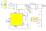
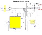
I have a dreamcast game console and the power supply works intermittently when it powers up cold. If I leave the ps on for about 20 sec, then it will work fine. The ps has 3 output voltages: 12V, 5V and 3.3V. The 3.3V output measured 2.5V and it caused the console to malfunction. The 12V and 5V rail work fine. The ps has one pwm controller chip and one isolation transformer.

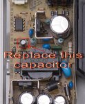
what possible bad component can caused the ps to malfunction when powering up cold? I already replaced the filter cap @ the 3.3V output but the problem persist.
 

Hi.

Assuming this picture is identical to your device. I would chechk the 3.3V voltage stabilisator. It may be a general voltage stabiliser that rely on external resistors to output the correct voltage. I guess that either one of the resistors is lose or defect or that the regulator itself is defect.

Chechk the soldering. It's a great chanse that applying fresh solder tin on the mentioned components would make it working again.
 

what and where is the voltage stabilizer on the ps board? Since you're from norway, I guess you use different terms.

Yes the picture you posted look exactly like the ps board that I have.

---------- Post added at 20:51 ---------- Previous post was at 20:49 ----------

what is the purpose of the three semiconductors (attached to heat sink) located @ lower half of the ps board?
 

I think those are the rectifiers that "rectify" or convert the high frequency AC to DC. I think those are ultrafast recovery or schottky diodes. 3 for 3 voltage rails.

Hope this helps.
Tahmid.

---------- Post added at 01:59 ---------- Previous post was at 01:54 ----------

Or the bottom 2 (the ones on one heatsink) could be paralleled for higher current capacity. Do they have 2 or 3 pins? I can't tell from the picture. Could you see it in your PSU?
 

Replace the capacitor marked in the attached picture.
 

Attachments

  • Sega-Dreamcast.jpg
    Sega-Dreamcast.jpg
    120.5 KB · Views: 153

Hi,

I would check with a ESR meter the capacitors near the output. If you do not have one, just change them! They are cheap.

Regards,
Bruno
 

what's your reason for replacing this cap? I just want to learn btw.
 

As we know the most common reasons that digital electronics devices fail seem to be a bad electrolytic capacitors. All aluminum electrolytic capacitors have a limited life span. And this occurs because heating of the electrolyte in the element, capacitors are not hermetically sealed, and the electrolyte in these capacitor eventually evaporates causing increased ESR which causes increased heating, and so on.
As you mentioned before you have already replaced the 3.3V capacitor and in this case need to replace the capacitor in the primary circuit also, next to the control circuit. I don’t have a schematics for this circuit, but I assume in the case of 5V&12V there are in between the transformer to outputs some additional circuits/transistors, that’s why no important variations seen as for the 3.3V output.
In general, you can either increase the voltage rating or the capacitance of the capacitor in a power supply application if you don’t find the exact values for. It is very important that you install the capacitors with the correct polarity.

why are some possible role/reasons of the additional circuits/transistors that you've mentioned?
 

Normally in a flyback SMPS only one output is regulated and the rest are just supposed to track, and if better regulation is required, then you need to add post-regulators. That’s the idea with additional circuits for +5V and 12V.
 

Attachments

  • SMPS flyback.JPG
    SMPS flyback.JPG
    41.6 KB · Views: 119
  • SMPS flyback 2.JPG
    SMPS flyback 2.JPG
    50.6 KB · Views: 120

thanks for the help. I think I found the problem. I took a closer look at the caps and I saw one of the caps had a leaky base (the 3.3V cap before the inductor). I will replace it and test the ps again.
 

if you want to check the esr of the capacitors (they are very often the main reason of actual electronis devices)
you can go to my website you will get schematics of esr meters from the simple one to the more complex one
regards,
**broken link removed**
 

Status
Not open for further replies.

Similar threads

Part and Inventory Search

Welcome to EDABoard.com

Sponsor

Back
Top