Continue to Site

Welcome to EDAboard.com

Welcome to our site! EDAboard.com is an international Electronics Discussion Forum focused on EDA software, circuits, schematics, books, theory, papers, asic, pld, 8051, DSP, Network, RF, Analog Design, PCB, Service Manuals... and a whole lot more! To participate you need to register. Registration is free. Click here to register now.

irfz44 Mosfet Failure

Status
Not open for further replies.

arup

Member level 2
Joined
Sep 6, 2004
Messages
46
Helped
0
Reputation
0
Reaction score
0
Trophy points
1,286
Activity points
441
Hi,

Application : micro controller based AMF relay(Genset Controller)
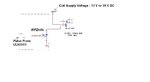
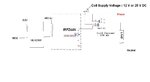
Please refer the attached file for exact application the way IRFz44N is used.The subjected MOSFET is driving a external relay ( Freewheeling diode might not used across the relay coil) which in turn will be used for driving START solenoid of generator or driving hooter or driving a contactor.The supply is 12 V / 24 Battery.I am driving the mosfet using a ULN with pulse amplitude of 5 V DC(max).I am getting frequent failure of this mosfet from the field.What could be the reason & what way i could protect the failure of mosfet.Pls suggest.


regds
 

Attachments

  • Application.JPG
    Application.JPG
    23.7 KB · Views: 221

The ULN2003 has open collector outputs so it can sink current from the gate (provide ground) but how do you source the current to the gate to turn it on.
You must have a resistor connected from the output of the ULN2003 , where is it connected?
The 5v pulses are in the gate or do you mean the ULN input?
Does the mosfet get hot?

Alex
 

Generally, a free-wheeling diode across the inductive load would effectively reduce transistor losses. Without it, the transistor is forced into avalanche breakdown of it's internal protection diode, dissipating the stored inductor energy. But IRFZ44 has a considerable avalanche energy rating and won't be damaged unless driving very large coils. So in my opinion, this point can't explain transistor failure. I would rather expect external shorts respectively wiring faults or extreme voltage transients causing it.

Of course, if a field technician realizes a wiring fault, do you expect that the cause of failure is correctly reported? They'll rather say, the device always failed unexpectedly. In this case, you may want to think about a true idiotproof design, involving short circuit and overvoltage protection.

ULN2003 gate drive would at least require a pull-up resistor and sounds odd.
 

If by pulse amplitude of 5V you mean the gate voltage maximum is 5V, then a logic level mosfet might be a better choice. IRLZ44 is one such mosfet.

John
 

Failure: what happens? shorted source -drain? or gate - source etc..
 

The ULN2003 has open collector outputs so it can sink current from the gate (provide ground) but how do you source the current to the gate to turn it on.
You must have a resistor connected from the output of the ULN2003 , where is it connected?
The 5v pulses are in the gate or do you mean the ULN input?
Does the mosfet get hot?

Alex

There is a pull-up resistance (of 3.3k to +5V dc.) to the signal connected between ULN ouput and IRFZ44N gate. The data for irfz44:
Id = 50 Amp
Vds = 55 V
Rds(on) = 17.5 mOhm

---------- Post added at 09:57 ---------- Previous post was at 09:46 ----------

Failure: what happens? shorted source -drain? or gate - source etc..

It shows resistance of only 7.8 ohms between drain & source and 153 kOhm between gate & source.So it should be source and drain shorted.

Regards,
arp
 

The Rds(on) is rated at a Vgs of 10V. Check Figure 1 in the datasheet. With a Vgs of 5 volts, the Rds is much higher. In other words, with the same Vds, current is about 9x greater with a Vgs of 10V versus 5V.

I have a difficult time understanding exactly how your devices are connected. It sounds like you are turning on the gate through a 3.3K resistor. That would lead to slow switching, which with the high Rds could be the reason for your device failing.

With a Vgs of 5V and any appreciable current, you need a logic-level mosfet.

John

Edit: Also, don't ignore post #3 about the diode.
 
Last edited:

The Rds(on) is rated at a Vgs of 10V. Check Figure 1 in the datasheet. With a Vgs of 5 volts, the Rds is much higher. In other words, with the same Vds, current is about 9x greater with a Vgs of 10V versus 5V.

I have a difficult time understanding exactly how your devices are connected. It sounds like you are turning on the gate through a 3.3K resistor. That would lead to slow switching, which with the high Rds could be the reason for your device failing.

With a Vgs of 5V and any appreciable current, you need a logic-level mosfet.

John

Edit: Also, don't ignore post #3 about the diode.

Pls see.exact connection is as per attached figure
 

Attachments

  • Application 1.JPG
    Application 1.JPG
    29.7 KB · Views: 98

Your mosfet is not turning on completely or quickly. The speed may not make much difference in this application. You were asked earlier, whether the mosfets get hot when they fail. If so, then look at the Vgs and be sure it is adequate. If not, then consider the inductive kick. Vdss is 55V; your supply can be 28V. A simple, fast diode across the relay may cure the problem.

John
 

All points, that have been said about suitable gate voltage level and switching speed are generally correct, but more or less meaningless for a 150 mA load driven by this "fat" transistor. They can hardly explain device failure.
 

Are you sure that the pullup resistor is connected to the 5v?
If you have it connected to +28v by mistake then the mosfet will be damaged.

Alex
 

same coil for either 28V or 12V operation ? does it mostly fail when its 28V ??
if assuming so, then the transistor may be dropping 16V across it.
0.15A (probably much more!) x 16V = 2.4W

won't that still need some heat dissipation ? maybe like one of those clip-on heatsinks ?
The enclosure could make a difference too....
And i've seen these transistors easily get hot when relying on its Vds breakdown voltage (55V) as a snubber.......
but for a relay, how often is it going to switch ?
 

same coil for either 28V or 12V operation ? does it mostly fail when its 28V ??
if assuming so, then the transistor may be dropping 16V across it.
0.15A (probably much more!) x 16V = 2.4W

Just because you have a 12v relay doesn't mean that the relay will have 12v and any remaining voltage will be dropped on the active element.
A 12v/0.15A relay has a resistance of about 80 ohm and the mosfet has an Rds-on less than 1 ohm (it will be much lower even with 5v Vgs) so if you put two resistors in series having 80 ohm and 1 ohm how much voltage do you expect to see on the 80 ohm resistor?
The only problem would be that the relay would overhead and get damaged because of excess current.

Alex
 

same coil for either 28V or 12V operation ? does it mostly fail when its 28V ??
if assuming so, then the transistor may be dropping 16V across it.
0.15A (probably much more!) x 16V = 2.4W

won't that still need some heat dissipation ? maybe like one of those clip-on heatsinks ?
The enclosure could make a difference too....
And i've seen these transistors easily get hot when relying on its Vds breakdown voltage (55V) as a snubber.......
but for a relay, how often is it going to switch ?

At present Relay coil is supplied by 12V DC only. This supply is 12 V , 150 Ah Battery and My device will act as generator set Start-Stop, Load transfer controller. The same battery will act as auxiliary supply for my device as well as external relay coil ( which will be used for driving START, STOP solenoid of gen-Set , driving AC contactor for load transfer etc).The coil current(hence Drain Current) could be Max 300 mA.
Would it be a reason that max Vds i.e 55 V is crossing for that device due to spike on Battery supply due to generator set operation.
Regds,
 

Vds of 55 V will be exceeded during each coil turn-off due to the lack of a free-wheeling diode. If you would want to reduce transistor stress, this should be changed first. But as I previously mentioned, this point still won't explain transistor damage in regular operation. Thus I'm still wondering if there's a hidden problem not shown in your schematic.
 

Status
Not open for further replies.

Similar threads

Part and Inventory Search

Welcome to EDABoard.com

Sponsor

Back
Top