Continue to Site

Welcome to EDAboard.com

Welcome to our site! EDAboard.com is an international Electronics Discussion Forum focused on EDA software, circuits, schematics, books, theory, papers, asic, pld, 8051, DSP, Network, RF, Analog Design, PCB, Service Manuals... and a whole lot more! To participate you need to register. Registration is free. Click here to register now.

burnt ic identification

Status
Not open for further replies.

jmindler

Newbie level 4
Joined
Jan 25, 2011
Messages
7
Helped
1
Reputation
2
Reaction score
1
Trophy points
1,283
Activity points
1,322
hello all,
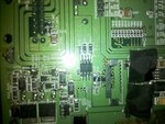
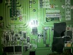
my son installed is car stereo, but he connected the power wires the wrong way. now the stereo does not work. I took it apart and found a what looks like a burnt ic. it has eight legs and the markings that I can make out are like this.
I R P647H
T1L6
F7205

any ideas.?

thanks
 

Can you upload a clear picture?
 

I wish I could. All you can see in the picture is a black square.

---------- Post added at 20:51 ---------- Previous post was at 20:33 ----------

I wish I could. All you can see in the picture is a black square.
 

Photos attached
 

Attachments

  • IMG_20110124_205012.jpg
    IMG_20110124_205012.jpg
    1 MB · Views: 266
  • IMG_20110124_205041.jpg
    IMG_20110124_205041.jpg
    1.1 MB · Views: 103

You need to turn off the camera flash and use another bright light at a different angle. Sometimes wetting the surface with some alcohol will help differentiate the markings enough to read. Use the macro or close up setting on the camera if it has one.
 

Thanks again. It is almost impossible to see any markings. I was able to make out the letters and numbers in the post before with a magnifying glass and bright light. The burning makes it hard to read the markings.
 

Hi,
this is a standard Mosfet in SO8 package.
Manufacturer: IR (International Rectifier)
PartNo: IRF7205
Datasheet: here
 

Any recommendations on where to get a new part? Thanks
 

Thanks for the help. I ordered the part last night. I was going to use a small soldering pen to remove and reinstall. Is that the best method? Hopefully, this will repair his radio issue. A lesson learned about polarity :)
 

You want to use a soldering tip that is slightly thinner than the component lead if possible. You need to have solder wick and know how to use it. To avoid having to heat all leads simultaneously to remove the chip, it's often easier to cut the leads off one at a time near the body of the chip with small wire cutters or carefully with a knife. After that you can use the soldering iron and solder wick to pick up the individual leads and clean the lands to prepare for the new chip.

This video is a good tutorial on beginning surface mount soldering: YouTube - Chaîne de CuriousInventor.

Be sure to orient the chip with pin 1 at the correct end.
 

Status
Not open for further replies.

Similar threads

Part and Inventory Search

Welcome to EDABoard.com

Sponsor

Back
Top