Continue to Site

Welcome to EDAboard.com

Welcome to our site! EDAboard.com is an international Electronics Discussion Forum focused on EDA software, circuits, schematics, books, theory, papers, asic, pld, 8051, DSP, Network, RF, Analog Design, PCB, Service Manuals... and a whole lot more! To participate you need to register. Registration is free. Click here to register now.

Need a short beep circuit

Status
Not open for further replies.
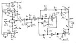
You're a genius! I tried a 100 uF capacitor between the +5 and 0 volt lines and I was still getting some minor modulation, so I tried a 470 uF and it works great.

With IC1 put back in place, the sensor works as expected.

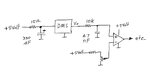
If I put the 10k pull up resistor between the IC1 output and +5v, I get the motorboating sound. Without the resistor, no motorboating and no ill effect.

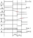
I just did some voltage tests on the circuit, measuring between Ground and A.

Without the resistor and no object in front of the sensor, I get 0.05 volts.
With an object in front of the sensor, I get 3 volts.
Everything sounds normal.

With the 10k resistor in place, I still get 0.05 volts with no object in front of the sensor and a motor boating sound. But when I place my multimeter probe at A to check the voltage, the motor boat sound stops.
Place an object in front of the sensor and I get 5 volts, crisp and clear.
Remove the object, with the multimeter probe in place, Tone G sounds funny, like it's oscillating between two notes, but stops after a second and it's silent.
Remove the probe and it's back to motorboating.

Do I *need* the pull up resistor if it appears to be working without it?
 

My wife opened this post for me & when she saw the first sentence she said "He knows that" (family joke, long story).

I can see why it works without the 10 k, but it is marginal. I would be happier if you include the 10 k.

So I suggest that you introduce some hystersis. See the attachment. By adding the resistors, you will have about 50 mV of hystersis. You may have to move the pot a fraction to compensate.

This will turn the comparitor into a Schmitt Trigger and this should eliminate the motor boating. However, I don't quite see why removing the 10 k stops the motor boating, so I may be wrong.
 

Attachments

  • Schmitt Trigger.gif
    Schmitt Trigger.gif
    3.3 KB · Views: 80

I wish I could reply with some good news, but adding in the resistors gives the same result.

I've visually gone over the entire circuit, checked to make sure everything is where it should be, and verified that the proper resistors are used, but everything checks out.

I agree that the motor boating must be coming from the IC1, since the problem isn't there when the IC is removed or bypassed. I swapped out the LM393 with a second LM393 (just so I wouldn't have to move any wires over to the other side) and the same thing happens. I could try using the comparator on the other side of the IC.

I thought that the other component I haven't looked at is the Pot. With the circuit powered, I take a voltage reading from Gnd to the center tap and I get 0.4 volts, which is what I want. I thought .. maybe if I replace the pot with suitable resistor(s), it might help? I pop the pot out and connect some resistors in series to give the same ohms that I was getting before (52.4 Kohm, including the 47K before the pot). And it doesn't work. I take a voltage reading and I'm getting 5 v at the reference input of IC1. Do I need a resistor to ground? One side of the pot is grounded, but my series of resistors isn't.
 

The pot is not the problem. A resistor to gnd would probably work as it will simulate the effect of your meter, but I would prefer to find a proper solution.

I think the sensor must be involved also. It is difficult to be sure given that I don't have a copy of its circuit. Do you? As far as I can see, the positive feedback involves both IC1 & the sensor.

A few possible solutions come to mind.

Try this first. Swap the inputs to the "Schmitt" over so the 10 k resistor is going to the pot and the - input is going to the sensor. This should make the feedback negative and thus prevent the put-put.

This will of course, invert the logic (ie. you will have to hold your hand over the sensor initially and then move it away to make the tone start), but that can be fixed later. The main issue is to resolve the motor boating.
 

I finally have some good news to report. Or at least some advancing in a forwardly direction :)

I don't have a copy of the circuit in the sensor, just the block diagram from the datasheet (see link below).

I thought that the feedback must have been coming from the sensor. My loving wife bought me an Arduino Uno for Christmas and I plugged a sensor into the analog input and read the sensor's output on the Serial Monitor. The range of the analog input is 0-1023 and I was getting readings from 0 to 700-something, jumping all around and not consistent. Even with my hand over the sensor, it would give me mainly higher-numbered readings, but still jumping around a lot.

I found these datasheets: GP2Y0A21* datasheet and Application Note, Data Sheet, Circuit, PDF, Pinout | Datasheet Archive
and in the second one (ANALOG Replaced PQ030EZ01ZPH), with the Frequently Asked Questions, Page 4, #12:
When I hook up GP2Y0A02YK0F I see a lot of noise on the line, how do I get rid of this?
SHARP recommends using RC filters on Vcc and Vo as called below. The R and C values are recommended starting points you can adjust as needed for your application.


I don't have 10 ohm resistors, just 15 ohm, so I adjusted the capacitor values to compensate and guess what! It works! Almost. Hystersis is removed (since it was added to try to compensate for the motor boating). Now the only thing is that Tone F lasts for about 1 second after A is grounded (object in front of sensor removed), there's a short pause before Tone G plays for 1 second. On Vcc of the sensor, I have a 15 ohm resistor and 220 uF capacitor. On Vo of the sensor, I have a 15 ohm resistor and 33 uF capacitor. I switched to a 22 uF capacitor and Tone F plays for a shorter duration, but not by much. A 10 uF capacitor (with a 15 ohm resistor still) plays Tone F for about as long as Tone G, even with a quick wave. I kind of like that. If someone walks slowly through the doorway, it'll play F for as long as they are there, but if they run through it will still play the Tone F for a reasonable length of time.

As for the silence between the notes. If I wave my hand over the sensor to play Tone F, it plays it and then nothing. If I move my finger just on the edge of the sensor's view, not enough to trigger Tone F, but just outside of that, A is grounded and Tone G plays.

Does that mean one of the capacitors is holding on to a little bit of electricity to prevent A from going low?

It's hard to get a voltage reading on the output of IC1 between notes because as soon as I place my probe on it, it grounds A. If I leave a probe on the output and wave my hand over the sensor, it functions like I'd like.

OH, and I should probably mention .. I don't know if this adds to the complexity of the circuit, but I'd ultimately like two sensors going to the circuit to monitor two doorways. Would it work to just have two inputs going to IC1? Or would I need to use the other comparator for the second sensor, and then both outputs tied together? Or through diodes?
 

I finally have some good news to report. Or at least some advancing in a forwardly direction :)

I don't have a copy of the circuit in the sensor, just the block diagram from the datasheet (see link below).

I thought that the feedback must have been coming from the sensor. My loving wife bought me an Arduino Uno for Christmas and I plugged a sensor into the analog input and read the sensor's output on the Serial Monitor. The range of the analog input is 0-1023 and I was getting readings from 0 to 700-something, jumping all around and not consistent. Even with my hand over the sensor, it would give me mainly higher-numbered readings, but still jumping around a lot.

What is a "Arduino Uno"?

I found these datasheets: GP2Y0A21* datasheet and Application Note, Data Sheet, Circuit, PDF, Pinout | Datasheet Archive
and in the second one (ANALOG Replaced PQ030EZ01ZPH), with the Frequently Asked Questions, Page 4, #12:
When I hook up GP2Y0A02YK0F I see a lot of noise on the line, how do I get rid of this?
SHARP recommends using RC filters on Vcc and Vo as called below. The R and C values are recommended starting points you can adjust as needed for your application.


Excellent! I see what is happening now. The DMS samples frequently & this is what your hearing as the putt-putt. See my attachment re the noise filter.

I don't have 10 ohm resistors, just 15 ohm, so I adjusted the capacitor values to compensate and guess what! It works! Almost. Hystersis is removed (since it was added to try to compensate for the motor boating). Now the only thing is that Tone F lasts for about 1 second after A is grounded (object in front of sensor removed), there's a short pause before Tone G plays for 1 second. On Vcc of the sensor, I have a 15 ohm resistor and 220 uF capacitor. 15 Ohm/330 uF would do just as well, in fact slightly better.

On Vo of the sensor, I have a 15 ohm resistor and 33 uF capacitor. See my attachment, in your case, the same can be achieved with a smaller cap & larger Res.

I switched to a 22 uF capacitor and Tone F plays for a shorter duration, but not by much. A 10 uF capacitor (with a 15 ohm resistor still) plays Tone F for about as long as Tone G, even with a quick wave. Are you sure it is 15 Ohm, it sounds more like 15 k to me given the times you're quoting?

I kind of like that. If someone walks slowly through the doorway, it'll play F for as long as they are there, but if they run through it will still play the Tone F for a reasonable length of time. See my comments below.

As for the silence between the notes. If I wave my hand over the sensor to play Tone F, it plays it and then nothing. If I move my finger just on the edge of the sensor's view, not enough to trigger Tone F, but just outside of that, A is grounded and Tone G plays. I don't understand this.

Does that mean one of the capacitors is holding on to a little bit of electricity to prevent A from going low? See my comment above re 15 Ohm vs 15 k.

It's hard to get a voltage reading on the output of IC1 between notes because as soon as I place my probe on it, it grounds A. This is odd. What is the resistance of your mulitmeter? It should be at least 1 MegOhm and should therefore not affect the voltage at A.

If I leave a probe on the output and wave my hand over the sensor, it functions like I'd like.

We can adjust the circuit later to make it work as you want. Let's sort out these issues first.

OH, and I should probably mention .. I don't know if this adds to the complexity of the circuit, but I'd ultimately like two sensors going to the circuit to monitor two doorways. Would it work to just have two inputs going to IC1? Or would I need to use the other comparator for the second sensor, and then both outputs tied together? Or through diodes?
I designed it so that Tone F plays for as long as the sensor output is high. But this can be changed.

2 sensors is not a problem, but let's sort out the other issues first.
 

Attachments

  • DMS connections.jpg
    DMS connections.jpg
    58.6 KB · Views: 76
Last edited:

The Arduino Uno is an open source, open hardware microcontroller. It has analog input/outputs, digital input/outputs, etc. You write the program using a simplified C++ language and upload it to the board, then it runs the software. The simplest program would make an LED blink. For many projects, it works well with a breadboard. I've seen videos online of people who use it to make a robot.

For the resistors and capacitors, I'll stop by the electronics store tomorrow to pick them up. I don't have the capacitors in my supplies.

I double checked the resistors and I'm using 15 ohm, not 15 Kohm. I used my multimeter to check. I had to double check in case I missed the 'K' on the display.

My multimeter is a Fluke 177, and their site says the maximum resistance is 50 Mohm.

To explain a little further about the high note/low note, depending on where I place my finger. I don't understand it, either, but with the sensor on my table, pointing up to the ceiling, if I place my hand above it (within 24 inches of it), the high note places as long as my hand is there. This is normal. I remove my hand quickly and the high note stops after about a second (with my current configuration and not the new RC values of your recent attachment). Then there is no sound. If I slowly move my hand toward the beam of the sensor (it uses infrared light), about 12" above it, before I get in the path of the beam (where it measures the distance to my hand), the low note will play. It's like with a high powered flashlight pointed at a wall, there's a bright spot in the center, the spill around it and nothing around the spill. If I move my hand into the spill, the low note plays. Move my hand into the spot, the high note plays. If I move from the spot to the spill, the high note plays followed by the low note.

I don't know if the infrared has a spot and a spill, of course, but that sort of explains what I do and how the circuit reacts. It's not a desirable outcome, so I'm hoping that by changing the capacitors, it'll fix that. I'll report back tomorrow. If it doesn't, I'll record a video if it'll help.
 

The Arduino Uno is an open source, open hardware microcontroller. It has analog input/outputs, digital input/outputs, etc. You write the program using a simplified C++ language and upload it to the board, then it runs the software. The simplest program would make an LED blink. For many projects, it works well with a breadboard. I've seen videos online of people who use it to make a robot. I use PIC microcontrollers. I programme them in assembly, I don't know C.

For the resistors and capacitors, I'll stop by the electronics store tomorrow to pick them up. I don't have the capacitors in my supplies.

I double checked the resistors and I'm using 15 ohm, not 15 Kohm. I used my multimeter to check. I had to double check in case I missed the 'K' on the display.

My multimeter is a Fluke 177, and their site says the maximum resistance is 50 Mohm.

I think that is the maximum resistance it can measure. I wanted to know the resistance of the meter when it is set in the voltmeter mode. I expect it is 1 Meg or more.

To explain a little further about the high note/low note, depending on where I place my finger. I don't understand it, either, but with the sensor on my table, pointing up to the ceiling, if I place my hand above it (within 24 inches of it), the high note places as long as my hand is there. This is normal. I remove my hand quickly and the high note stops after about a second (with my current configuration and not the new RC values of your recent attachment). Then there is no sound. If I slowly move my hand toward the beam of the sensor (it uses infrared light), about 12" above it, before I get in the path of the beam (where it measures the distance to my hand), the low note will play. It's like with a high powered flashlight pointed at a wall, there's a bright spot in the center, the spill around it and nothing around the spill. If I move my hand into the spill, the low note plays. Move my hand into the spot, the high note plays. If I move from the spot to the spill, the high note plays followed by the low note.

This is very odd, something is amiss. See below.

I don't know if the infrared has a spot and a spill, of course, but that sort of explains what I do and how the circuit reacts. It's not a desirable outcome, so I'm hoping that by changing the capacitors, it'll fix that. I'll report back tomorrow. If it doesn't, I'll record a video if it'll help.
Given that you told me in a previous post that putting the meter probe on A to measure the voltage effectively makes it low, then something is wrong. If the meter resistance is say 1 Meg, then the current through the 10 k would be about 5 uA. Thus the voltage drop across the 10 k would be about 50 mV. Thus the meter should read 4.95 Volt - assuming that the 5 Volt is exactly 5 Volt.

But to make A low, the voltage would have to drop to less than the lower threshold level of the 74HC14 - see its data sheet. From memory, it is typically about 1.5 Volt.

Therefore, I suspect that the 10 k resistor that is connected between +5V and A is open or not properly connected.

You can check this as follows. Set the meter into the current mode.

Connect one probe on Gnd and the other on A. It should read about 0.5 mA if the resistor is OK.

I suggest you measure it either on the input pin of IC2a or on the left hand end (looking at my circuit) of the 220 Ohm.

Don't touch the 10 k with the probe as - if there is a bad connection - touching it may temporarily fix the bad connection thus giving a misleading result.
 

In case I wasn't clear earlier, putting the probe on A doesn't keep A low. If I have the probe on A (even without the other probe grounded), it makes the circuit work properly. Without it, I put my hand over the sensor and I get the high note (IC2d). Remove my hand and it goes silent. I'm not sure for how long, but for at least 30 seconds. I put a probe on A, or even on the output of the IC1, and the low note (IC2e) plays. Keep the probe on A, place my hand over the sensor and the high note plays. Remove my hand and the low note plays immediately. That's why I say it seems to ground A, because A needs to be grounded out for the low note to play, right?

I added the resistors and capacitors as per your most recent drawing. The high tone plays for only as long as my hand is in the sensor, not extended for a second anymore.

I replaced the 10K pullup resistor with another, and another still, but I'm still getting the same results. I'm afraid I don't know how to fully utilize my meter. When you say to put it into current mode, I have AC current in A or mA. That wouldn't be the same thing, would it?
 

In case I wasn't clear earlier, putting the probe on A doesn't keep A low. If I have the probe on A (even without the other probe grounded), it makes the circuit work properly. Without it, I put my hand over the sensor and I get the high note (IC2d). Remove my hand and it goes silent. I'm not sure for how long, but for at least 30 seconds. I put a probe on A, or even on the output of the IC1, and the low note (IC2e) plays. Keep the probe on A, place my hand over the sensor and the high note plays. Remove my hand and the low note plays immediately. This is very odd. It still seems to me that the 10 k is open. That's why I say it seems to ground A, because A needs to be grounded out for the low note to play, right? Correct

I added the resistors and capacitors as per your most recent drawing. The high tone plays for only as long as my hand is in the sensor, not extended for a second anymore. That is how it should be. As I said previously, this feature can be included in the final design quite easily.

I replaced the 10K pullup resistor with another, and another still, but I'm still getting the same results. I'm afraid I don't know how to fully utilize my meter. When you say to put it into current mode, I have AC current in A or mA. That wouldn't be the same thing, would it?
I've attached a scan of 3 pages from the handbook of one of my meters.

You need DC current, not AC (unless your meter can automatically change to suit the input)

Note the input impedence on page 4. Also note that on page 6, the low current ranges have a fuse. So if your meter will not read current in these ranges, check the fuse.

I suggest you:-

1. check the 10 k res as I suggested last time.

2. restore the hystersis resistors on IC1. See if this makes a difference. (I would have inserted hystersis if I designed this part of the circuit)

3. set your meter to DC Volts and measure the voltage at A with and without the sensor triggered.
 

Attachments

  • Page 4.gif
    Page 4.gif
    15.6 KB · Views: 68
  • Page 5.gif
    Page 5.gif
    20.7 KB · Views: 84
  • Page 6.gif
    Page 6.gif
    20.3 KB · Views: 75

I found the manual for my meter online. It has >10 Mohm Input impedance, and the fuses check out good.

I also figured out how to switch from AC A to DC A .. it was a button that the label was worn off (my meter was given to me used), and I had to switch the red probe to another socket.

1. I tested A, at a few different points just to be sure, and I get 0.77 mA.

3. Set to DC Volts, at A it's 0.045 volts without the sensor triggered and 5 volts when it is triggered.

2. Regarding adding in the Hystersis. I have a 10K resistor (and 47 nF capacitor) from the sensor output to the IC1 + Input for the noise filter. Am I supposed to add another 10K resistor? I added the 1 Mohm between the + input and the Output of IC1. I tested it without the second 10K and then added in a 10K. So, from my sensor output, it goes through a 10K resistor. On the other side of the resistor, a 47 nF to gnd (noise filter) and a 10K to IC1 + input.

With the second 10K and the 1M in place, the high note plays. The 'silence' before the low note now sounds like screeching tires of a car. But it pulses, so it's like Anti-lock brakes, and the car won't stop until I place my hand just outside the beam's view, as before.

Is there a way to test just a resistor? I'm still getting 10 Kohm (roughly) with my meter, and I've swapped out a couple of 10 K resistors for it.
 

I found the manual for my meter online. It has >10 Mohm Input impedance, and the fuses check out good.

I also figured out how to switch from AC A to DC A .. it was a button that the label was worn off (my meter was given to me used), and I had to switch the red probe to another socket.

1. I tested A, at a few different points just to be sure, and I get 0.77 mA. That is near enough. It should be closer to 0.5 mA, but your meter may have drifted a little, given its age.

3. Set to DC Volts, at A it's 0.045 volts without the sensor triggered and 5 volts when it is triggered. Good.

2. Regarding adding in the Hystersis. I have a 10K resistor (and 47 nF capacitor) from the sensor output to the IC1 + Input for the noise filter. Am I supposed to add another 10K resistor? I added the 1 Mohm between the + input and the Output of IC1. I tested it without the second 10K and then added in a 10K. So, from my sensor output, it goes through a 10K resistor. On the other side of the resistor, a 47 nF to gnd (noise filter) and a 10K to IC1 + input.

With the second 10K and the 1M in place, the high note plays. The 'silence' before the low note now sounds like screeching tires of a car. But it pulses, so it's like Anti-lock brakes, and the car won't stop until I place my hand just outside the beam's view, as before.

Is there a way to test just a resistor? I'm still getting 10 Kohm (roughly) with my meter, and I've swapped out a couple of 10 K resistors for it. It is best to disconnect one end of a resistor to test it. If you measure it in circuit, it may give misleading results.
I realised what the problem is last night.

I think the comparitor is oscillating. The comparitor is an amplifier with a very high gain.

Therefore, it can be unstable under certain conditions.

So I suggest that you connect the 47 nF (ie. the filter cap) to the - input and the 10k (the one from the + input) to the pot.

This will invert the logic (as I said in an earlier post) but we can correct that later. The main issue at this point is to prove whether it works properly with this configuration.

So ignore the inverted logic for the moment and let me know what happens.
 

So .. basically, the pot to + Input. The Sensor, through the noise filter and the 10K for the hysteresis to the - Input. In effect, just swapping the inputs to get the inverted logic?

I did that and the circuit works invertedly (is that a word? haha). The high note is on constant, I put my hand over it and the low note plays for about a second and stops. No other unwanted noises.
 

Excellent.

I'll post a circuit for you later today.

Here it are, drawn with a thumb nail dipped in tar.
 

Attachments

  • Waveforms 2.jpg
    Waveforms 2.jpg
    98 KB · Views: 75
  • Circuit 2.jpg
    Circuit 2.jpg
    97.3 KB · Views: 64
Last edited:
  • Like
Reactions: Kolero

    Kolero

    Points: 2
    Helpful Answer Positive Rating
Wow, we've come a long way from an oscillator and a 4017, haven't we? I'll post when I've finished it. Thank you very much!
 

Wow, we've come a long way from an oscillator and a 4017, haven't we? I'll post when I've finished it. Thank you very much!

You're welcome.

Note that I just replaced the circuit with a new version as I had drawn D5 the wrong way around.
 

I have very good news to report! The circuit works fabulously!

Now for the final touches:

If I understand it right, if I want to shorten the length of the first tone, after the sensor goes low, I can use a smaller resistor for R1. And to shorten the length of the second tone, that would be R2, correct?

The speaker output seems okay, but if I want to boost it, would I use a transistor? I have three to choose from: 2N2222, 2N3904 and 2N4401. Is there a difference?

And, if I want the second note to fade out instead of stopping abruptly, is that difficult to add in?

I'm excited that I'll soon be able to put this into a project box and call it done :)
 

That's good.

Yes, the length of Tone 1 is determined by R1 & C1.

The length of Tone 2 is determined by R2 & C2.

I'll have a think about the other issues later.
 

Status
Not open for further replies.

Part and Inventory Search

Welcome to EDABoard.com

Sponsor

Back
Top