Continue to Site

Welcome to EDAboard.com

Welcome to our site! EDAboard.com is an international Electronics Discussion Forum focused on EDA software, circuits, schematics, books, theory, papers, asic, pld, 8051, DSP, Network, RF, Analog Design, PCB, Service Manuals... and a whole lot more! To participate you need to register. Registration is free. Click here to register now.

PS won't go to zero volts???

Status
Not open for further replies.

easilyconfused

Junior Member level 2
Joined
Jul 16, 2010
Messages
22
Helped
0
Reputation
0
Reaction score
0
Trophy points
1,281
Activity points
1,470
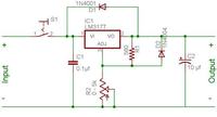
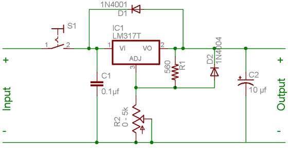
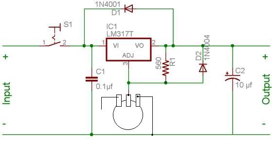
I used this schematic for building an adjustable power supply. I used precisely the components called for. Certainly I could've made a mistake. I'm still on the breadboard. It does work. And moving the pot does adjust the volts. But it only goes down to 1.25 volts instead of zero. What did I do wrong? My wall wart is rated for 12VDC/900mA. My output is 1.25v to 16v. Thanks for any help.


There is nothing wrong with this circuit ..
You just reached the bottom limit, which is +1.25V reference level, and you can't go lower than that ..
If you need the output voltage down to 0V you have to connect the bottom pin of the potentiometer to -1.25V, minus=negative ..

IanP
:D
 

IanP said:
There is nothing wrong with this circuit ..
You just reached the bottom limit, which is +1.25V reference level, and you can't go lower than that ..
If you need the output voltage down to 0V you have to connect the bottom pin of the potentiometer to -1.25V, minus=negative ..

IanP
:D

Thank you. I feel better knowing that I didn't make a mistake. But-- Am I wrong for wanting a power supply that goes all the way to zero? I wanted to show my grandson how voltage climbing from zero to "some voltage" will begin passing through diodes.

I told you previously that I followed the schematic precisely but that's not exactly true, or "may not" be true. I didn't know what to do with the third leg of the pot so I left it open. I don't know how to do as you suggested. Can you tell me what to connect that leg to in order to get it to go to zero. Or should I simply accept it as having minimum of !.25v? Thanks very much for you time.

Here is the schematic showing my pot hook-up. As you can see-- one leg is just flappin' in the breeze. I wouldn't know where to connect it for the neg 1.25v you mentioned.
 

The voltage between Vo and ADJ is always 1.25V ..
That’s the reference voltage for the LM317 ..
So, if you put the ADJ pin at 0V level the output pin Vo will have 1.25V ..

As I mentioned before, in order to adjust the output voltage to 0V you need to fulfil the 1.25V difference rule and set the ADJ pin down to -1.25V ..
Question is, where would you make this -1.25V available from?
For a test purposes you can use 1.5V battery and connect it in such a way that it will provide -1.5V reference for the ADJ pin, or if connected via a potentiometer, will allow you to adjust the voltage down to 0V (and a little bit below, -0.25V) .. see attached picture .. (also have a look how the third pot’s pin is connected, it can be left unconnected – it doesn’t matter)

Or should I simply accept it as having minimum of !.25v?
Then, after demonstration, you can remove this battery from the circuit and the minimum output voltage will be 1.25V ..


IanP
:D
 

IanP said:
Then, after demonstration, you can remove this battery from the circuit

Thank you! Thank you! Thank you! Even I can understand that.
 

Status
Not open for further replies.

Part and Inventory Search

Welcome to EDABoard.com

Sponsor

Back
Top