Continue to Site

Welcome to EDAboard.com

Welcome to our site! EDAboard.com is an international Electronics Discussion Forum focused on EDA software, circuits, schematics, books, theory, papers, asic, pld, 8051, DSP, Network, RF, Analog Design, PCB, Service Manuals... and a whole lot more! To participate you need to register. Registration is free. Click here to register now.

Help me with a clapp oscillator design

Status
Not open for further replies.
Re: capacitor doubt

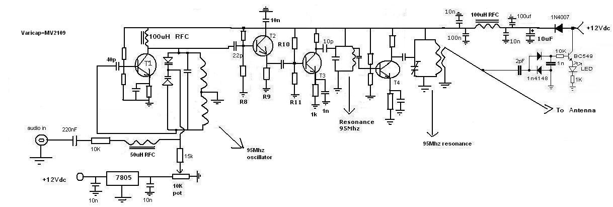
Without a feedback path it will not work. One side of the tuned circuit is grounded.

You would do better to return to the original oscillator circuit but READ THE COMMENTS made earlier about stabilizing the oscillator supply and connecting the varactor(s).

Note: you have two short circuits across the supply, the output is connected to the supply line and the output matching circuit is still wrong.

Brian.
 

capacitor doubt

here i have made a oscillator around hartely oscillator
please
tell me is the grounding is correct and is there any shorting of the varactor in this circuit
 

capacitor doubt

The oscillator might work but the coils in the amplifier short-circuit the supply voltage to ground.
 

Re: capacitor doubt

Emphasis on the oscillator 'might' work. The DC connection from the T1 collector to the top varactor might stop it working. Over at least part of the range of the 10K pot it will be forward biased and conducting.

The rest still has the shorts though so there's no chance of it producing a signal.

Brian.
 

capacitor doubt

sorry friends i forgot to include a cap at the T1's collector,here is the new one


Added after 1 minutes:

now i think there will be no shorting in the oscillator part...

Added after 2 minutes:

and please tell me that does that pi network is correct and does it work,if no please tell me how to solve it

Added after 2 hours 13 minutes:

here is Low pass filter which filters signals from 91Mhz to 101Mhz,see if that works
 

capacitor doubt

The pi networs are lowpass filters. But the oscillator output has a big signal level that cannot be amplified anymore. The pi lowpass filters will have the same or slightly lower amplitude as the oscillator so the high voltage gain of T3 and T4 are not needed and cannopt be used.

But if T3 and T4 had a tuned parallel LC filter at their collectors then the signal can swing to double and more of the amplitude of the lowpass filters.
 

Re: capacitor doubt

As Audioguru says, a pi network is not appropriate between T3 and T4.

There are two advantages to pi networks, firstly they allow the input and output impedances to be individually matched while maintaining resonance and secondly they work as low-pass filters above the resonant frequency so they suppress harmonics. The is no point in suppressing harmonics between T3 and T4 as they will almost certainly be re-introduced by T4 again. Your pi network seems to have extra components too. They are called pi networks because they look like the Greek letter pi (Π) with two upright capacitors and an inductor across the top. The antenna can connect to the output of the pi network without a secondary winding.

Your new oscillator design may actually work but you would do better to return to your original design but follow the advice you were given at the time. You should also stabilize the oscillator supply voltage and remove the 7805 regulator.

Brian.
 

capacitor doubt

the power supply for the transmitter is given From a SMPS(mercury).
it has 12V,5V and 3.3V stabilized power supply.

Added after 34 minutes:

and here are two bandpass filter with different configuration, which can filter frequency range from 91Mhz to 101Mhz.
which one is best
1) " **broken link removed** "
or the 2nd one
2) " https://www.flickr.com/photos/aj_silverthunder/4203303043/sizes/o/ "
please help me to select the best for FM signal filtration
 

Re: capacitor doubt

Why do you want a bandpass filter? It is not the circuit to use in this application.

I very much doubt that the stability of your SMPS is good enough for the oscillator, in fact it will probably have enough noise on it to interfere with the oscillator running properly. The frequency is dependent on the supply voltage so if you have noise or any variation in voltage it will cause FM modulation. This is not what you want.

Use the 12V as the main supply, use a 7809 or 7805 regulator to drop and stabilize the oscillator supply. It will be stable enough that you can use it to provide your tuning control voltage as well so you save some components.

Take a look at https://www.smeter.net/amplifiers/pi-network-rf-amplifier-output.php and download the program at the bottom of the page for pi network calculations. Note that the RFC at the output is NOT part of the tuned circuit and you can leave it out altogether in your application. The load resistor is your antenna.


Brian.
 

capacitor doubt

but some say that band pass filter is used to filter out the harmonics and give a clean signal
 

capacitor doubt

If the transistor is linear then an LC tuned circuit at it collector will filter out harmonics and allow its collector voltage to swing up to double the supply voltage.

If the transistor is pulsed in class-C then an LC tuned circuit at its collector will filter out harmonics and allow its collector to swing up to much more than double the supply voltage.
 

capacitor doubt

friends i have used both band pass filter and Pi network in this circuit
band pass filter to "filter the harmonics" and Pi network to match the impedance to a 50ohm or a 300ohm antenna.
please check it out ,and tell me any errors
 

Re: capacitor doubt

Now you have a 101MHz NON-transmitter :|

You need to learn what inductors and capacitors do. Just as importantly, you need to understand the properties of series and parallel tuned circuits.

Go Google for the properties of tuned circuits.

Brian.
 

capacitor doubt

The output level of the oscillator is high so T3 is not wanted since all it does is create many harmonics.

Your parallel LC tuned series circuit blocks the signal.

This thread is a nightmare of errors.
 

capacitor doubt

Transmitter Macro Diversity in DBV-T, i am currently working on this topic using matlab simulink i am trying to add fadding model in the existing model in simulink is any body help me thanks
 

capacitor doubt

sorry thats a notch filter between T3 and t4,it used to pass other frequencies except the frequency of the interest.sorry guys here i have corrected it


Added after 1 minutes:

audioguru as u told this thread is a nightmare of threads,but atlast as high quality circuit will come out from here,and i have confidence,i just need u r help
 

capacitor doubt

I said it before.
Remove T3 and its parts because the output of the oscillator and T2 are at a high level then T3 makes nothing but overdrive harmonics.
 

capacitor doubt

friends i have completed the circuit,check it and find out any errors.


Added after 4 minutes:

a multimeter can read ac voltage till 750V,but my doubt is can a multimeter detect RF waves,for example when the probe is touched to the output of a FM transmitter,(multimeter set to read AC voltage),will it show and value maybe (-) or (+) any value even 0.02. or will it not give any readings.
and doing this does the RF wave damage the digital multimeter?
and as a multimeter can read frequency till 1000Hz,so a RF signal diode(PIN diode) can convert RF singal into DC then feeds it to a DC current meter (100uA range) can do the job that was expected earlier expected. and the DMM can be used to detect RF, do u feel it works guys
 

capacitor doubt

Most cheap digital multimeters measure only the 50Hz or 60Hz mains frequency accurately.
They are not accurate at 1kHz and cannot measure radio frequencies.
 

Re: capacitor doubt

Feeding RF power into a DVM might damage it but it would depend on lots of factors. It certainly wouldn't measure the RF voltage directly though.

A better method than measuring the diode current is to rectify the RF and measure it's voltage. If you know the voltage and the load impedance you can use Ohms law to calculate the power.

I still think your output coupling is far from optimal and it still has a DC short across the supply lines.

Brian.
 

Status
Not open for further replies.

Similar threads

Part and Inventory Search

Welcome to EDABoard.com

Sponsor

Back
Top