Continue to Site

Welcome to EDAboard.com

Welcome to our site! EDAboard.com is an international Electronics Discussion Forum focused on EDA software, circuits, schematics, books, theory, papers, asic, pld, 8051, DSP, Network, RF, Analog Design, PCB, Service Manuals... and a whole lot more! To participate you need to register. Registration is free. Click here to register now.

Help me with a clapp oscillator design

Status
Not open for further replies.

aj_silverthunder

Full Member level 3
Joined
Jul 30, 2009
Messages
179
Helped
0
Reputation
0
Reaction score
0
Trophy points
1,296
Location
asia
Activity points
2,601
capacitor doubt

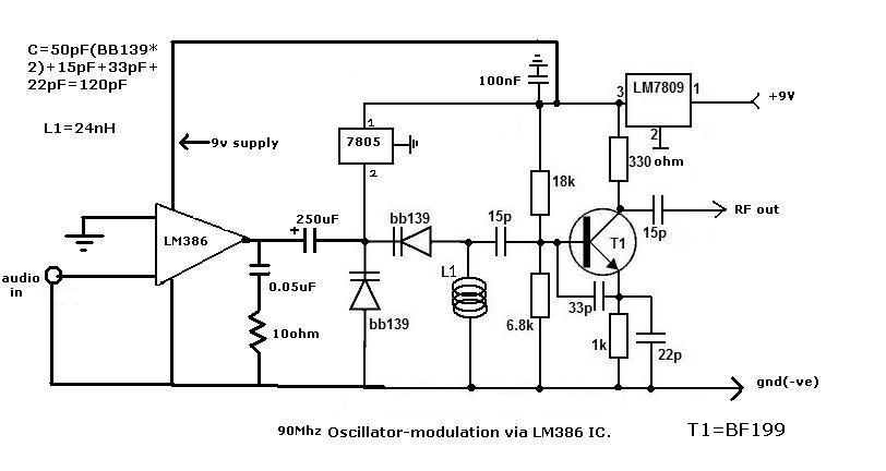
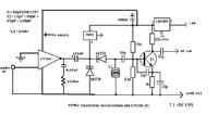
GUYs tell me does this oscillator works and do think its a clapp oscillator!.
2)and the main doubt is that does that 250uF cap also add its capacitance in the oscillator to produce HF.but if it adds ,the frequency becomes will be very low,if it does not add,what is the reason behind it that it does not add its capacitance to the oscillators!...


capacitor doubt

I don't see an oscillator because there is no positive feedback.
I see the output of an LM386 power amplifier trying to drive the dead short of the output of a 5V regulator that feeds 5V to two varactor diodes.
The extremely low impedances of the output of the power amplifier and the 5V regulator are shorting the varactor diodes.

The 9V regulator will not work unless its input is at least 10.5V or more.
 

capacitor doubt

https://www.flickr.com/photos/aj_silverthunder/4168982201/

Added after 11 seconds:

The oscillator is a clapp oscillator that is meant to be frequency modulated by the two varactor diodes. The oscillator is designed to transmitt on the FM band (88 MHz to 108 MHz). The LM 386 op amp output is coupled by the 250 uF capacitor to the junction of the varactor diodes. The audio output voltage is supposed to vary the diodes capacitance and therefore vary the oscillators frequency. However the varactors are biased with a LM7805 five volt regulator, this regulator will hold the voltage on the varactors at 5 volts preventing the audio from the op amp to vary the voltage across the varactors. If you build this circuit add a 1k ohm resistor between the 7805 and the junction of the varactors.
The 22 pf and 33 pf capacitors provide the positive feedback which allows the oscillator to oscillate. The output from the transistor's emitter is fed back to its base. The inductor L1 resonates with the 3 series capacitors (15pf, 33pf + the parallel transistor's base emitter capacitance,22pf) in parallel with the two series varactor diodes. The 18k and 6.8k resistors set the transistor bias. The oscillator output is taken off the collector by 15pf capacitor.

Added after 1 minutes:

Audioguru said:
I don't see an oscillator because there is no positive feedback.
I see the output of an LM386 power amplifier trying to drive the dead short of the output of a 5V regulator that feeds 5V to two varactor diodes.
The extremely low impedances of the output of the power amplifier and the 5V regulator are shorting the varactor diodes.

The 9V regulator will not work unless its input is at least 10.5V or more.
are u not able to see 33pF and 22pF caps for positive feedback!
observe it clearly!

Added after 58 minutes:

how can the 5 volt short the two varicap diodes,the maximum voltage rating of BB139 is 30V!
 

Re: capacitor doubt

aj_silverthunder said:
http://www.flickr.com/photos/aj_silverthunder/4168982201/

how can the 5 volt short the two varicap diodes,the maximum voltage rating of BB139 is 30V!
The AC output impedance of the 5V regulator is a dead short. You are supposed to feed 5V through a series resistor to the vari-caps. The resistor prevents the shorting.
 

capacitor doubt

if i add a 1k ohm resistor between the 7805 and the junction of the varactors. that will avoid shorting!am i right!
or can i increase the value of the resistor to 10K ohms .what do u say audio guru...
i am really thanbkful to u bcause u helped me lot to learn!
please tell me if i place a 1K resistor from 7805 to the varactors,will it avoid shortingh..please help me !
 

Re: capacitor doubt

aj_silverthunder said:
if i add a 1k ohm resistor between the 7805 and the junction of the varactors. that will avoid shorting!am i right!
or can i increase the value of the resistor to 10K ohms .what do u say audio guru...
No.
1k is far too low. The original circuit had 56k. it also had a 100k resistor from the audio source.
 

capacitor doubt

As already mentioned by "Audioguru" the vari-cap diodes are connected to regulated 5v volts directly which will never work. Another point to be noted is that LM386 output which can drive a speaker, is directly connected for diode intersections which will over modulate the audio...Cheers
 

Re: capacitor doubt

Audioguru said:
aj_silverthunder said:
if i add a 1k ohm resistor between the 7805 and the junction of the varactors. that will avoid shorting!am i right!
or can i increase the value of the resistor to 10K ohms .what do u say audio guru...
No.
1k is far too low. The original circuit had 56k. it also had a 100k resistor from the audio source.
so then will i place a 56K inbetween 7805 and the varactor diodes!

Added after 5 minutes:

pranam77 said:
As already mentioned by "Audioguru" the vari-cap diodes are connected to regulated 5v volts directly which will never work. Another point to be noted is that LM386 output which can drive a speaker, is directly connected for diode intersections which will over modulate the audio...Cheers
but if i will use 100K preset to lower the audio power from LM386!
and i can control the modulation level!
 

Re: capacitor doubt

aj_silverthunder said:
but if i will use 100K preset to lower the audio power from LM386!
and i can control the modulation level!
No.
The original circuit has a line-level input. The LM386 is an amplifier that makes the signal too high. The 100k resistor reduces the signal level only a little.

If your audio signal is at line level then you do not need an amplifier.
 

Re: capacitor doubt

aj_silverthunder said:
but if i will use 100K preset to lower the audio power from LM386! and i can control the modulation level!
The cicruit requires just low level input, even directly from a condensor mic or with one stage of amplification will work fine. Why to amplify with LM386 and drop it with resistors again?...cheers
 

capacitor doubt

please tell me how would this oscillator work,its still more developed than before one
 

capacitor doubt

It uses an old medium power transistor (2N2219) but it has the same low output power as the one before.
Get rid of the LM386 power amplifier. It is made to drive a speaker, not for driving a transmitter.

The LED is backwards.
 

capacitor doubt

tell me how is the frequency stability of the oscillator!
 

Re: capacitor doubt

aj_silverthunder said:
tell me how is the frequency stability of the oscillator!
It is probably poor because the antenna connects directly to the oscillator and anything that moves toward the antenna or moves away will change the capacitance of the antenna and transistor which will change the frequency of the oscillator.
 

capacitor doubt

the output from the antenna will be given as input to a 20Watt RF power amplifier!

Added after 1 hours 57 minutes:

here i have modified the circuit!
tell me is there any problem with it!
 

capacitor doubt

You changed the original circuit too much:
1) You cannot tune it because you removed the tuning pot.
2) You cannot modulate the vari-caps because you added the very high value 60pf capacitor in parallel with them.
 

capacitor doubt

check this one!
how about this one

Added after 30 seconds:


Status
Not open for further replies.

Similar threads

Part and Inventory Search

Welcome to EDABoard.com

Sponsor

Back
Top