Continue to Site

Welcome to EDAboard.com

Welcome to our site! EDAboard.com is an international Electronics Discussion Forum focused on EDA software, circuits, schematics, books, theory, papers, asic, pld, 8051, DSP, Network, RF, Analog Design, PCB, Service Manuals... and a whole lot more! To participate you need to register. Registration is free. Click here to register now.

AC phase shift 180 degree

Status
Not open for further replies.

walker5678

Full Member level 3
Joined
May 17, 2006
Messages
179
Helped
7
Reputation
14
Reaction score
3
Trophy points
1,298
Activity points
2,493
op amp dc bias phase shift

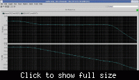
I encountered a strange thing when analyzing the opamp's AC characteristic, that the AC phase plot start from -180 degree at DC frequency, and begin to increase to -170, -160... etc.
And the pz analysis showes there is a RHP pole.
But when decrease the supply voltage, the AC plot returns to normal.
The OP amp's circuit has been proved on other process, and i just want to migrate it to another process.
Any one meet the similar thing?

Thanks
 

0 to -90 degree phase shift

-180 degree is actually same as +180 degree in AC simulation.
 
0 to 180 degree phase shift schematics

yes.
But 180 is also incorrect, it should start from 0, right? What confused me is that why the opamp generate a 180 phase shift at DC frequency, and how the RHP pole emerge?

 
Last edited by a moderator:

180 degree phase shift current

Probably your output is referred to the inverting input?
In this case the -180° phase @DC is correct (or +180°, as leo says).
 

180 phase shifter

I add the AC source at the positive input, so the output should be 0 phase shift at DC.
 

180 phase shift

walker5678 said:
I add the AC source at the positive input, so the output should be 0 phase shift at DC.

If it´s really a problem for you, you should post the circuit schematic.
Probably the bias point is not correct; in such a case an ac analysis shows incorrect or strange results. Example: If an opamp with feedback is unstable, an ac analysis nevertheless can show results which seems to be OK but are incorrect.
 

180 degree phase shift

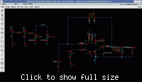
attachment is the schematic and simulation circuit.


Last edited by a moderator:

opamp phase shift 180

Hi walker5678,

two questions:
1.) Why Vdd/2 at the pos. input ? Do you have single supply (cannot be recognized in your schematic) ?
2.) For what purpose is the capacitor at the neg. input ? (Normally, it causes instabilty because the loop gain decreases with 40 dB/dec!!)
 

The feedback network is 10G, 10F only effective at DC bias. It's apparently a method to set up an open loop measurement and should be O.K. for this purpose (at least with neglectible input current).The said phase response should be expected as an effect caused by part of the OP not correctly biased at present supply conditions. I'm not an IC design guy, but I would check all transistor currents and voltages, most likely you'll find some devices shut off.
 

Only now - after reading FvM´s comment - I´ve realized the values within the feedback network. OK, there will be no HF instability because of the large C=10 Farad.
But I doubt if you really can establish a suitable bias point with a resistor
of 10 GIGAOHMS.
 

Unfortunately, i checked all the operating point and found there is no transistor working in linear region. The RC network can establish DC point well.
The phase plot showes there is a RHP pole, and the pz analysis also prove this. +++so maybe there is a negative ac resistance when vdd greater. but how the RHP pole emerge??

BTW, the opamp is single supply powered.
 

At what VDD level do the AC response waveforms return to normal?
Also, can you post the "normal" magnitude and phase responses?

P.S. In case you figured it out, what was it?
 

At about 4.5V, the curve returns to normal.

This is the normal curve.

 
Last edited by a moderator:

OK, got it, tahnks. Is the change gradual with VDD, or is it happening on the spot?

Also, I would suggest a DC sweep of VDD from 4.5V to 5.5V and look for changes in the biasing condition of the op-amp. I would expect to see something, if we are to belive that something is wrong with the circuit. If no change occurs, it could be a simulator thing. However, let's not jump ahead too much and wait for the results.
 

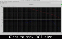
The change is gradual with VDD. see below pic. . Sweep vdd from 4V to 5V.


And another strange thing is that when the AC analysis start from 0.001Hz, the DC phase start from +180 degree, but not -180 degree. See blow pic.


I checked the operating point when the curve is normal and abnormal, found they are almost the same.

And the transient step analysis, the close loop AC analysis, and the sine wave transient response all showes there is no problem near the DC frequency.

And changed to other processes, like TSMC, SMIC, the problem does not exist. Maybe the reason is really about model.
 

hello,
i just noted that ur gnd is global in the test bench however, u connected the Opamp gnd to net named vssa, could u please show the rest of the testbench
 

Hi walker5678,

as mentioned already in my reply on 24th of dec., I doubt if 10 Gohms can give you a good bias point. Remember, a bias current of 1nA produces a voltage of 10 volts at the opamp input.!
 

LvW,

This was my worry as well. However, the response from walker5678 is that the operating point is good and it does NOT change when sweeping from 4 to 5V.

But again, in the interest to put this to bed completely, could you please walker5678 run a sim with the 10G resistance reduce to 10Meg?


walker5678,

One more thing: although gradual, the change occurs in a span of 20-40mV. Pretty small! Please do not take this personally, but have you plotted different bias voltages versus VDD to see that nothing changes dramatically?

Thanks,

ict_eda
 

Hi, LvW
Below is the pic. with the DC operating point annote. The bias point is 2.5007V, which is normal.


Hi, ict_eda:

what do you mean by saying "bias voltages"? I sweeped the bias current from 5u to 20u, the problem is the same.

Thanks for your suggestions
walker
 

I think, the input current is simply zero for the involved transistor model, and thus you can use any feedback resistor without causing bias point problems.

To repeat a previous, apparently yet ignored suggestion, you can trace the AC signal through the amplifier stages to see, where the strange effect occurs. Apart from a possible real bias point problem observable in an amplifer stage, I wonder if we may face a simple case of an inappropriate tolerance parameter for the DC bias point solver, causing inplausible operation conditions for an individual part, not visible in the output bias voltage?
 

Status
Not open for further replies.

Part and Inventory Search

Welcome to EDABoard.com

Sponsor

Back
Top