Welcome to our site! EDAboard.com is an international Electronics Discussion Forum focused on EDA software, circuits, schematics, books, theory, papers, asic, pld, 8051, DSP, Network, RF, Analog Design, PCB, Service Manuals... and a whole lot more! To participate you need to register. Registration is free. Click here to register now.
Simplest way to expain will be combining of three different inputs and then putting them on three outputs. So the outputs are the same that is combined signal of the three input ports.
Please see the attached file in an application to get more idea about it.
I want to know if the 3x3 hybrid combiner can design only by hybrid coupler? I do it for a long time ,the 3x3 hybrid combiner cann't design by coupler.what device can i add to design.
Don't quite understand your so-called "3x3 matrix hybrid coupler".
I used to design a Ka-band 1-3 coupler (19~21Ghz), which does have 6 ports, 3 on each side, but only the center port (P2) of one side is designed as input, the other two (P1 and P3) are perfect-loaded. Of course side ports (P1 and P3) can also be designed as inputs, but more complicate due to insymmetrical structure.
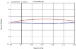
I attached a semi-optimized response (4.77dB optimal), redline is S25 and blue lines are S24 and S26. Multi-branchline structure are also attached.
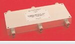
what I meant is a hybrid coupler has 3 inputs ports and 3 outputs, see the attachments for detail. Anybody know the inner structure of this combiner? Any tip will be really appreciated.
I have designed a 3x3 Wideband Hybrid matrix and also 3x3 Combiner (for split bands).
But the wideband hybrid design is such, it has un-equal power split at the output ports.
You will have Out-1 as 3dB, Out-2 and Out-3 as 6dB theoretically as it depends on whether you are looking for a equal split coupler or unequal split!!!!
If it has to be equal split, you need to use back to back connected directional couplers of '4.78dB' and '3dB' to achieve an equal split coupler particularly for wideband (800-2500 MHz)
If the design is for split bands, you can use either lange coupler or branchline coupler (Two 3dB couplers and one 4.78dB coupler) design to achieve equal split between output ports.
This site uses cookies to help personalise content, tailor your experience and to keep you logged in if you register.
By continuing to use this site, you are consenting to our use of cookies.