Continue to Site

Welcome to EDAboard.com

Welcome to our site! EDAboard.com is an international Electronics Discussion Forum focused on EDA software, circuits, schematics, books, theory, papers, asic, pld, 8051, DSP, Network, RF, Analog Design, PCB, Service Manuals... and a whole lot more! To participate you need to register. Registration is free. Click here to register now.

PicKit 2 FULL with TH components - Need help with layout

Status
Not open for further replies.
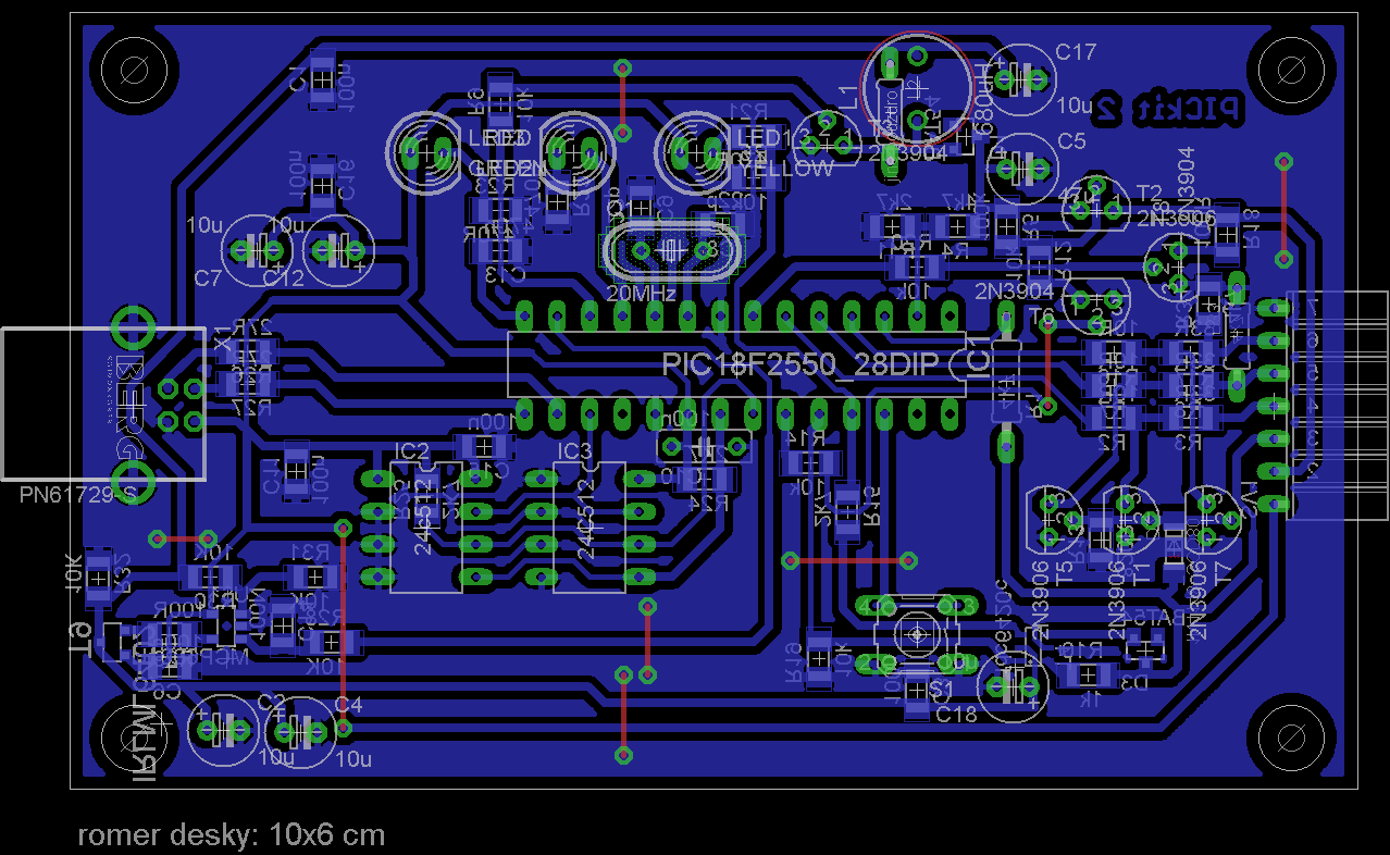
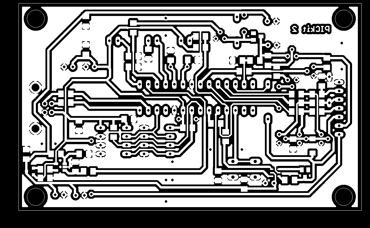
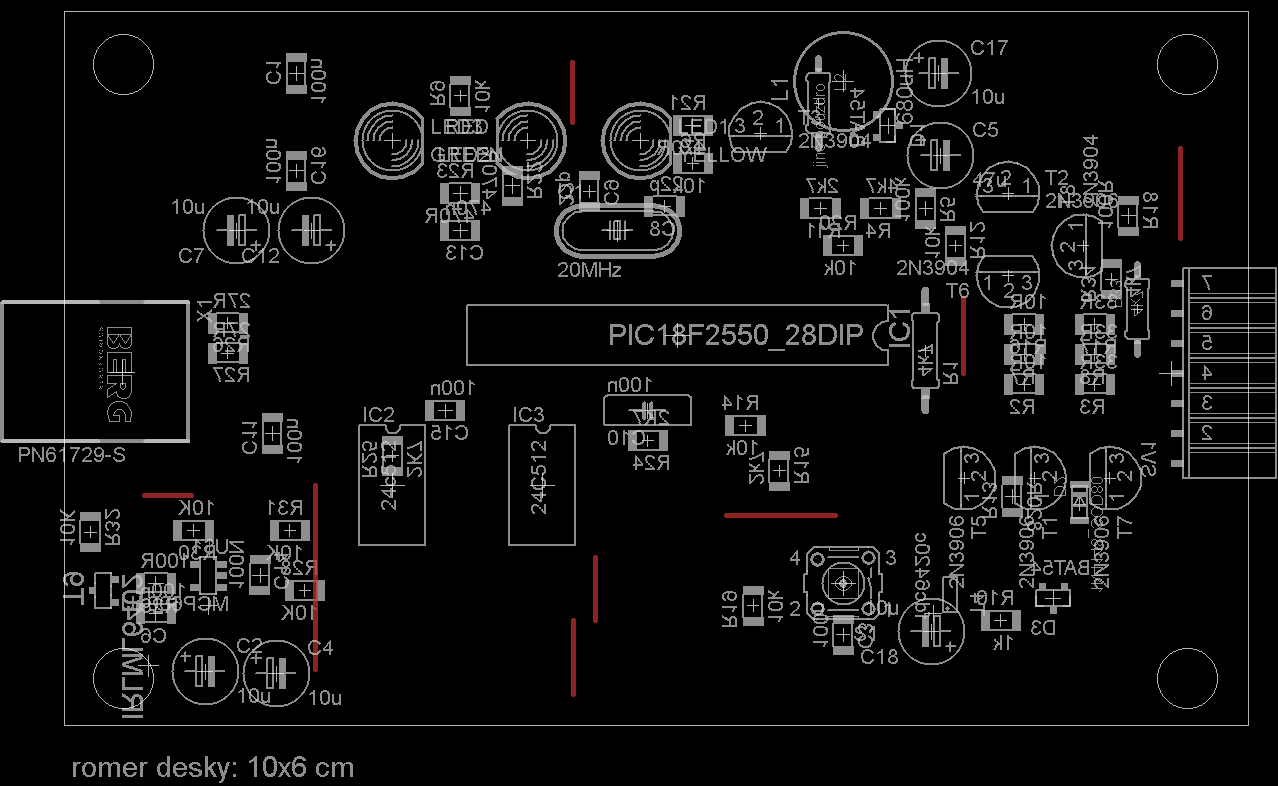
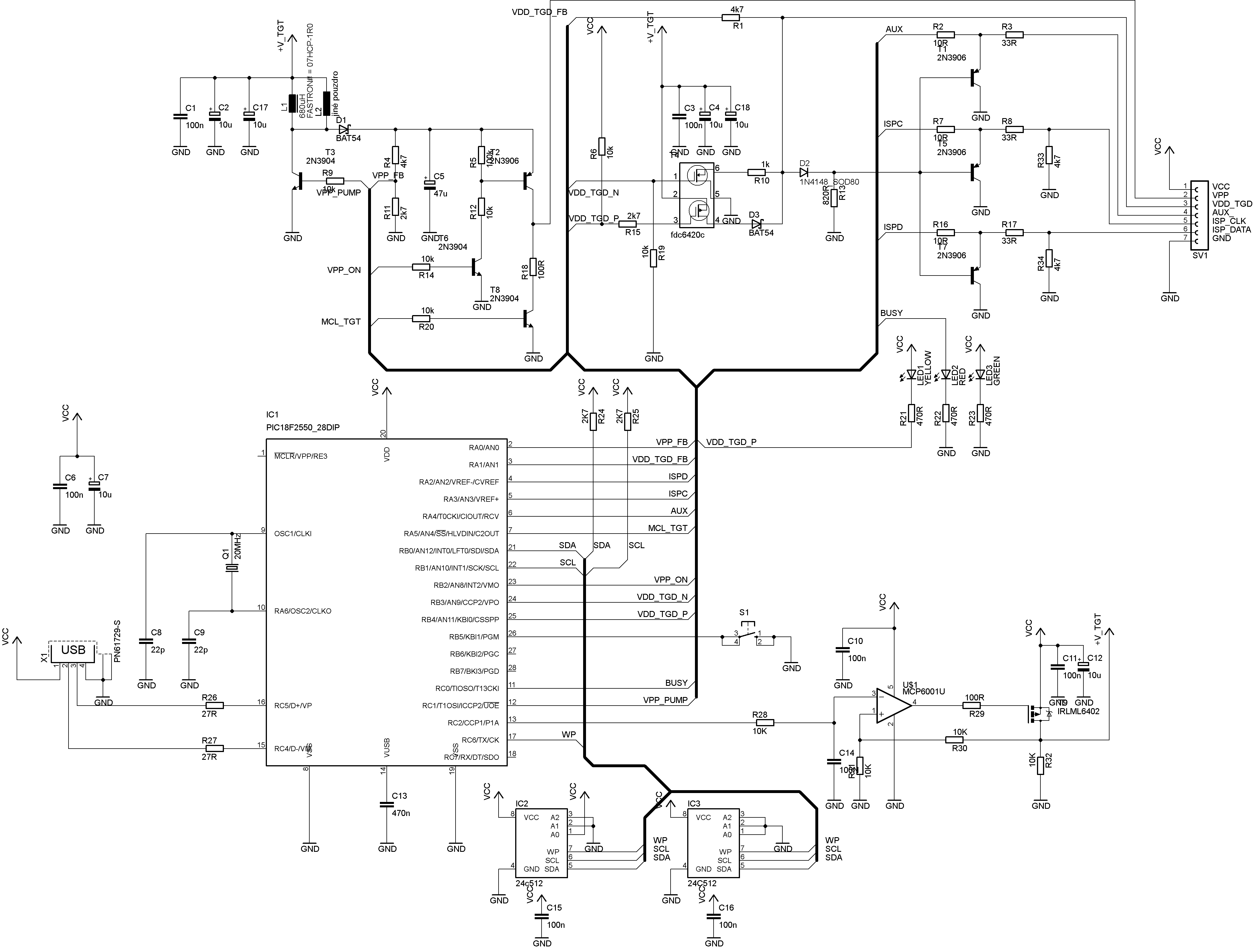
I just edited the symbol, Now I found that these pins have direction
is this going to matter much? how to edit package?
 

Corrected library for MCP6001R
Please check. Hope this is right now.
 

Attachments

  • Pickit2.rar
    9.5 KB · Views: 149

Uploaded New Board layout and circuit and ready to print PDF files with original smd and through hole components.
Need your comment and suggestions.
 

Attachments

  • PICKIT2.rar
    112.1 KB · Views: 210

this schematic lacks few resistors like 4.7K at the output to ground for clock and data pins. these are needed for some functions as per the pickit2 user manual.
perhaps the designer has skipped them for reasons known to him

Sorry, these resistors I forgot and I add to schematic. Here is a corrected version.;-)

View attachment correct_eagle_6.1.0.rar

**broken link removed**
 
Last edited:

Please check for proper polarity of pins of the MOSFETs used. while soldering some reversals possible. ensue this aspect
I could do the crosscheck of layout and the schematic if you could mail me directly at mvs_sarma(at)yahoo.com
 

Please check for proper polarity of pins of the MOSFETs used. while soldering some reversals possible. ensue this aspect
I could do the crosscheck of layout and the schematic if you could mail me directly at mvs_sarma(at)yahoo.com
hi, linkan,

how come the 8th wonder (unless phished my account), that you could receive messages on my account??
this very mvs_sarma@yahoo.com created and used by me was phished around two years back. if accidentally, it is under your control, i would request you, to surrender it to me.

thanks.
 

Sorry, these resistors I forgot and I add to schematic. Here is a corrected version.;-)

View attachment 76398

**broken link removed**

Sorry, i dont have eagle ver 6 . my present ver5.11.0 cant open your files. you may perhaps post a pdf copy of sch and brd so that some study can be meade if you need more help.
 

Sorry, i dont have eagle ver 6 . my present ver5.11.0 cant open your files. you may perhaps post a pdf copy of sch and brd so that some study can be meade if you need more help.

There is a picture. Resolution is a 300dpi.


and this picture "http://obrazki.elektroda.pl/4_1340916834.png" invert color in "for example" mspaint. ;-)

coils L1 and L2 are identical, just another case. ;-)
 
Last edited:

Hello, I must ask for some help

I have read many forums and articles about various pickit2 clones build some of them on test board but still have no appropriate result so I finally redraw microchip schematic with components that I can find but I’m not sure that I use right ones so if You can look at my schematic and tell me is correct or should I change something.

PS.
I cannot find MCP6021 in my country so I plan to use OP07 Linear op-amp is that correct? Or should I use some other Opamp

Thanks in Advance

Schematic in PDF

View attachment Pic2CloneFull.pdf
 

@ Jirkaj.
looks neat. but if i understand the purpose of electrolytic and dic de coupling capacitors, they are to clean the supply line of the ac return path of the activity going on section wise.
Thus it becomes imerative to place them close to the subsecti9ons , like Vdd adjust, Vpp genererator, Vdd target switching , mian control chip ate. But I find that they are place one besiude the other at same place. Please try to readjust them judiciously.


@snm_za,
As per Section 1 of your schematic,

A. C7 (0.47uF) can be a box type or ceramic capacitor.
B. The LED series resistors can be increased to 1K each and it helps reduce load on the Vusb.
C. Q1 (Pmos) might be a problem and i Had to switrch over to IRLML6402. Later i got a cheaper NDS356 with better quality (lower ON resistance)
D. the Op amp must be a Rail to rail type. Thus OP07 would not work. google for raqil to rail opamp and check what you could lay hands ON.
I was using MCP6271 or MCP6281 from microchip. But there are many from TI, ST, ONsemi etc...


As per section2,
1. R10, R14 and R19 need to ne corrected to 10 ohms and NOT 10K.

2. PGD and PGC need a terminating resistor each of 4K7 which are missing. They are needed

3. Q21 and Q22 might trouble you as they have high ON resistance. We had problems with them. I my self reverted to Si2302 (Nmos) and DS356 (Pmos)

4. Q4, Q7 and Q8 cvan be BC547, if you don't get 2N3906.

5. Q4 base was driven by (R21) 1K resistor in original design , please check.

6. ICSP pin connections are wired different from what is shown in black text adjescent. Perhaps you can go for a original microchip standardconnector BERG female 6 way.


All thge best.
 
  • Like
Reactions: snm_za

    snm_za

    Points: 2
    Helpful Answer Positive Rating
First I want to say THANK YOU for Yours support!

Now more questions :)

A: I put wrong symbol on my schematic and wrong value should be ,47uF
B: good suggestion
C: Any suggestion for TH component
D: Totally missed :oops: will try to find MCP6271 or similar
Section 2
1. My mistake wrong value :oops:
2. I cannot find those resistors on original document from microchip
3. Any suggestion for TH component
4. I already have BC547 but no problem to buy 2n3906
5. In original document that I have , it is 10k maybe is print error
6. I plan to use 10x flat cable with connector for ICSP connector with one row
1.MCLR, 2.Vdd, 3.GND, 4.PGD, 5.PGC, and second row with AUX

And once more THANK YOU


C. you might have problem if the ON resistance is high. mouser, Farnel, etc sell the SMDs. they can be glued behid the board with one or two pins manged and other pin(s) extended by a small wire. Otherwise change the component in artwork once you get the item in market.

2. these resistors are thyere in the sch found on the userguide. of PICKIT2.
3. comment , same as at C above.
4. BC547 amounts to 2N2904 with proper orientation. BC557 is pnp and they can well be used in place of 2N3906 again with orientation .
5. as I see the user guide i find that Q4 is driven by 1K. check here --DS51553E-page 78 R21 value 1K. if any later change is there by microchip
i would love to have that document.

all the best SNM_ZA,
 

First I want to say THANK YOU for Yours support!

Now more questions :)

A: I put wrong symbol on my schematic and wrong value should be ,47uF
B: good suggestion
C: Any suggestion for TH component
D: Totally missed :oops: will try to find MCP6271 or similar
Section 2
1. My mistake wrong value :oops:
2. I cannot find those resistors on original document from microchip
3. Any suggestion for TH component
4. I already have BC547 but no problem to buy 2n3906
5. In original document that I have , it is 10k maybe is print error
6. I plan to use 10x flat cable with connector for ICSP connector with one row
1.MCLR, 2.Vdd, 3.GND, 4.PGD, 5.PGC, and second row with AUX

And once more THANK YOU
D>>>you can use MCP601/2/3/4, MCP6001/2/3/4 need one please ask I have plenty of them
 
Last edited:

perhaps YES. MCP 601 DIP can be placed directly. Other SMD devices, by improvisation on solder side. after all other than ground and supply, three wires.
 

Hey Guys...!!

I'm here after a long time. I see another member is trying to make the PicKit 2. Now that i have built my PicKit 2 and it is working perfectly i'm attaching some pics and the eagle files so that you guys can take a look at it and benefit from it... BTW i would like to thank Computerman29 for his great work and mvs sarma for sharing his valuable work with me and all the others who helped me to build and complete my PicKit 2. Thank you guys...!! :grin:


DSC01624_4104x3078.jpg DSC01630_4104x3078.jpg

Attaching two files

  1. PicKit 2 board
  2. Mini usb connector board

Note :
The Burg connector (Printer Port) foot print in my board has being modified to fit the mini usb connector board. So if you want to use a printer port please replace the Burg connector with your foot print (From your library) in the schematic.
 

Attachments

  • PicKit2 2012-02.rar
    172.9 KB · Views: 209
  • mini usb connector.rar
    6.7 KB · Views: 137

Re: pickit2 eagle

Dear Computer men... File attached is corrupted i think.... While opening Orcad file some errors appearing..BRD file too(I opened by Allegro 16x viewer) Cant get your files.. Kindly send working one... Thanks in advance
 

Status
Not open for further replies.

Similar threads

Part and Inventory Search

Welcome to EDABoard.com

Sponsor

Back
Top