umery2k75
Advanced Member level 1
ac dc ground
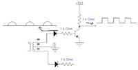
This is the diagram which is included in my project.The Vcc and Ground of transistor are of DC +5V and Gnd.Now I must get square wave of the half wave sinusoidal wave coming from AC source 220/50Hz.I wasn't getting neither the square wave and nor the sinusoidal.So I replace the NPN emitter ground with the AC ground, now I can see the pulsating DC on the cathode of the diode, but no square wave is outputing from the transistor collector.I have used different values of resistors.I don't understand as why the Ground of the DC power supply doesnot produces the pulsating DC at the cathode of the diode, I only get this when AC ground is connected.When dealing with center tap transformer, I put one black lead to the ground(middle one) and I measure voltage on the other two sides in AC mode, I get different values slightly altered.Although I bought the "6 0 6" transformer.As we get 6V on either side which are 180' out of phase.I read some what 7.80V and 7.85V
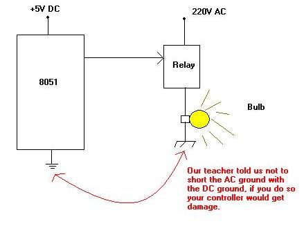
Can I connect the AC ground and DC ground together?
This circuit is very simple, I don't know why this is not working.
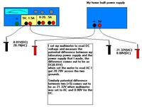
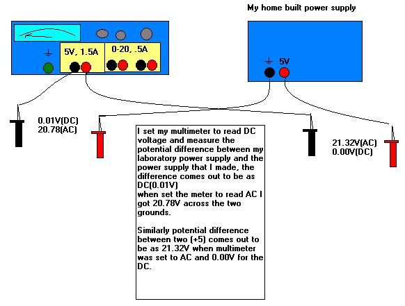
I also make the power supply for my project, I use the 220-12V transformer and 470uF capacitor on the 12V side, bridge rectifier and I use 7805 voltage regulator to get the +5V.
Please tell me as how can I get the square wave from this circuit and why my laboartory power supply and my home built power supplies have different values of AC/DC voltage when measured by multimeter.
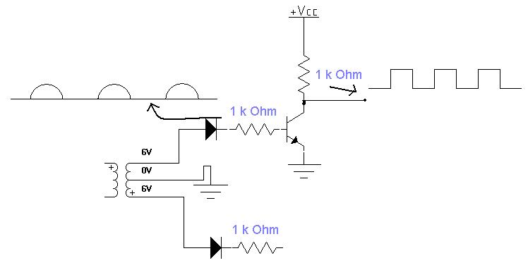
This is the diagram which is included in my project.The Vcc and Ground of transistor are of DC +5V and Gnd.Now I must get square wave of the half wave sinusoidal wave coming from AC source 220/50Hz.I wasn't getting neither the square wave and nor the sinusoidal.So I replace the NPN emitter ground with the AC ground, now I can see the pulsating DC on the cathode of the diode, but no square wave is outputing from the transistor collector.I have used different values of resistors.I don't understand as why the Ground of the DC power supply doesnot produces the pulsating DC at the cathode of the diode, I only get this when AC ground is connected.When dealing with center tap transformer, I put one black lead to the ground(middle one) and I measure voltage on the other two sides in AC mode, I get different values slightly altered.Although I bought the "6 0 6" transformer.As we get 6V on either side which are 180' out of phase.I read some what 7.80V and 7.85V
Can I connect the AC ground and DC ground together?
This circuit is very simple, I don't know why this is not working.
I also make the power supply for my project, I use the 220-12V transformer and 470uF capacitor on the 12V side, bridge rectifier and I use 7805 voltage regulator to get the +5V.
Please tell me as how can I get the square wave from this circuit and why my laboartory power supply and my home built power supplies have different values of AC/DC voltage when measured by multimeter.