mohammad hassanzade
Newbie level 6
- Joined
- Oct 2, 2010
- Messages
- 12
- Helped
- 1
- Reputation
- 2
- Reaction score
- 1
- Trophy points
- 1,283
- Location
- tehran,iran
- Activity points
- 1,362
hi
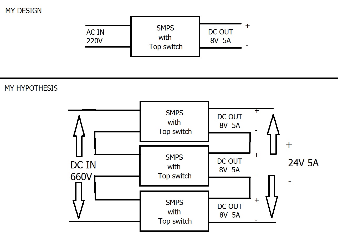
i can design a switching power supply with a top switch
rating this design :
220v input
8v 5a output
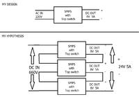
but now
i need a power supply converter 660v to 24v 5a
& i question from all friends:
can i do make 3 number of my design power supply in series mode connecting in input & output for achieve to 660v input power supply & 24v 5a output power supply?
tnx for your answer before answering
i can design a switching power supply with a top switch
rating this design :
220v input
8v 5a output
but now
i need a power supply converter 660v to 24v 5a
& i question from all friends:
can i do make 3 number of my design power supply in series mode connecting in input & output for achieve to 660v input power supply & 24v 5a output power supply?
tnx for your answer before answering