lenny9926
Newbie level 1
Hello to everyone,
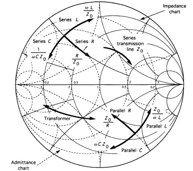
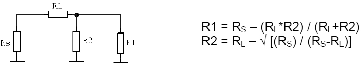
I would like to know if it is possible to replace inductors by resistor, and still use the Smith Chart Software to obtain S21?
Please be kind and explain the reasons.
I would like to know if it is possible to replace inductors by resistor, and still use the Smith Chart Software to obtain S21?
Please be kind and explain the reasons.