Continue to Site

Welcome to EDAboard.com

Welcome to our site! EDAboard.com is an international Electronics Discussion Forum focused on EDA software, circuits, schematics, books, theory, papers, asic, pld, 8051, DSP, Network, RF, Analog Design, PCB, Service Manuals... and a whole lot more! To participate you need to register. Registration is free. Click here to register now.

How to test a pulse transformer which is used in the VFDs (inverters) ?

Status
Not open for further replies.

munzir

Full Member level 6
Full Member level 6
Joined
Oct 11, 2011
Messages
365
Helped
22
Reputation
44
Reaction score
21
Trophy points
1,298
Location
Pak
Activity points
3,795
How to test a pulse transformer which is used in the VFDs (inverters) ? whether three phase output or a single phase output .........

How can i get to know that the pulse transformer is working and its firing the pulses at the gate of the SCR ?

thanks
 

Recent VFDs are using IGBTs or MOSFET output switches, not SCR. And they are rarely triggered by pulse transformers.
 
  • Like
Reactions: munzir

    munzir

    Points: 2
    Helpful Answer Positive Rating
Recent VFDs are using IGBTs or MOSFET output switches, not SCR. And they are rarely triggered by pulse transformers.

So what component(s) is used in recent VFDs to trigger the IGBTs or MOSFETs ????
 

There are special ICs for Gate triggering of IGBTs and MOSFETs, like, IR2110, TC4420, TC4429 and so on.............
 
  • Like
Reactions: munzir

    munzir

    Points: 2
    Helpful Answer Positive Rating
There are special ICs for Gate triggering of IGBTs and MOSFETs, like, IR2110, TC4420, TC4429 and so on.............

thanks

How can i get to know that the pulse transformer is working and its firing the pulses at the gate of the SCR ?
 

thanks

How can i get to know that the pulse transformer is working and its firing the pulses at the gate of the SCR ?

But after all , How can i get to know that the pulse transformer is working and its firing the pulses at the gate of the SCR ?
 

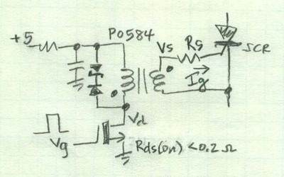
I don't exactly understand what you want to achieve. A pulse transformer is a passive component, that rarely goes bad. Much more likely the trigger generator will be defective.

But you can check the gate trigger pulses with an oscilloscope. You either need to disconnect the supply connection of the power circuit for measurement with a regular grounded probe or use an isolated differential probe.
 

what's the trigger generator ?

Is it connected with the pulse transformer (to the output of pulse transformer) ?

thanks
 

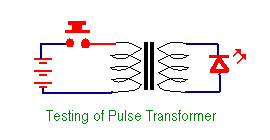
Disconnect pulse transformer from circuit, connect a led to output coil ,provide a dc pulse to input, see the led twinkle, if not, reverse led connections and recheck.
 
Disconnect pulse transformer from circuit, connect a led to output coil ,provide a dc pulse to input, see the led twinkle, if not, reverse led connections and recheck.

would you provide me the circuit by taking any particular example ?

thanks though
 

99_1321469601.png

LED should flash when push button is released after a few moment contact. If not connect LED in reverse direction or reverse the polarity of dc supply.This tests the function of pulse transformer.
 
Last edited:
Should i first close the push button for sometime & then release (open) the push button ?

There are 5 terminals on left side (primary side) & 5 terminals on right side (secondary side) ...... Where to connect + of the dc supply & - of the dc supply & also where to connect on secondary the led ?

Thanks a lot
 

Check with Multimeter on Primary side which pins show continuity there connect any side +ve. If there are tow primaries then connect center pin +ve and any one -ve. Same way check any winding's two pins on secondary side and connect LED on any winding. If the LED does not glow select the other pin on primary with center tap still connected.
 
  • Like
Reactions: munzir

    munzir

    Points: 2
    Helpful Answer Positive Rating
It seems like prior to testing, you should better identify the exact component type and connection scheme. There should a thing named data sheet. If not available at all, an ohmeter can help to figure out the windings configuration.
 

Check with multimeter and identify different sets of coil by their continuity. For half bridge drive, there are two windings reqired,one for each switch. If input drive is using push-pull tropology then there will be three terminals (centre tap winding ). By tracing circuit, actual windings used can be identified. There may be nc(not connected) terminals.
Pulse transformer is a passive compnent, its chances being faulty are less. physical stress can damage it(wire broken) or if excessive current passed through it.
Use a 100 ohm resistor in series with batery. Then use any winding to see the effect.
 

what is the trigger generator ?

what are the voltages present from anode to cathode of the thyristor ?

thanks
 

If for example you look at the datasheet of BT145 (thyristor) you will find some information in columns like:
BT145.jpg
Here you can see the Gate maximum voltage as 5 volts. So you will find this all basic information in the datasheet. My advice, please always consult the datasheet first you will find more than 50% answers in there.
The Trigger Generator: Is the circuit which generates the TRIGGER pulses to be fed in the Gate causing the Thyristor to conduct. This circuit is known as Trigger Generator.
 

don't you think that the pulse transformer is also the part of the trigger generator ?

thanks
 

Status
Not open for further replies.

Similar threads

Part and Inventory Search

Welcome to EDABoard.com

Sponsor

Back
Top